I2C Architecture
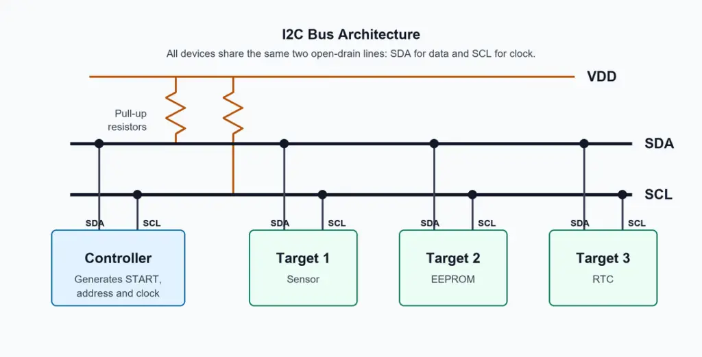
An I2C bus consists of one or more controllers and one or more target devices connected through the same SDA and SCL lines.
The architecture is based on a shared-bus model. All devices connect in parallel to the same two wires, so every device can observe bus activity. However, only the addressed target participates in a transaction. This makes I2C different from point-to-point interfaces where each peripheral needs a separate data path.
In a typical system, the controller is a microcontroller, processor, FPGA, or SoC block. Target devices can be sensors, memories, display controllers, power-management ICs, GPIO expanders, or other low-speed peripherals. The controller starts the transfer, sends the target address, decides whether the transfer is a read or write, and usually provides the SCL clock.
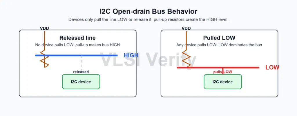
The bus is idle when both SDA and SCL are HIGH. Since the lines are open-drain, devices do not force a HIGH level onto the bus. Instead, pull-up resistors return the lines to HIGH when all devices release them. Any device can pull a line LOW, so LOW is the dominant bus state.
Each target device must have a unique address on the bus. If two devices respond to the same address, both may drive ACK or data at the same time, which can corrupt communication. Some devices provide address-select pins so multiple copies of the same IC can coexist on one bus.
The I2C architecture is best suited for short board-level connections. The maximum practical number of devices depends on address availability, bus capacitance, pull-up resistor value, wiring length, and selected speed mode.
Block Diagram
In older terminology, the controller is often called the master and the target is often called the slave. Many datasheets still use those names, but controller and target describe the same roles in more modern language.
SDA and SCL lines
SDA carries the address, data, and acknowledgement bits. SCL carries the clock used to synchronize data transfer.
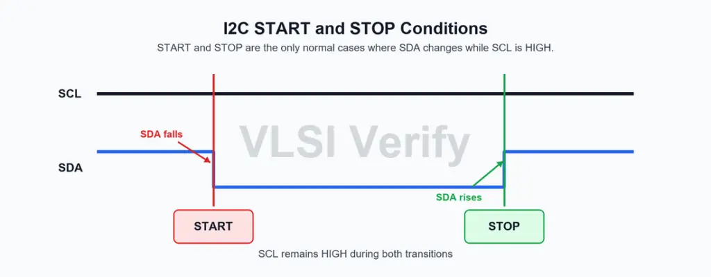
The controller usually generates the clock on SCL. During each clock cycle, one bit is transferred on SDA. Data on SDA must be stable while SCL is HIGH. SDA is normally allowed to change only while SCL is LOW.
Two special exceptions define the beginning and end of a transaction:
- START condition: SDA changes from HIGH to LOW while SCL is HIGH.
- STOP condition: SDA changes from LOW to HIGH while SCL is HIGH.
Open-drain bus and pull-up resistors
I2C devices do not actively drive the bus HIGH in normal operation. Instead, each device can pull SDA or SCL LOW, and external pull-up resistors bring the lines back HIGH when no device is pulling them LOW.
This type of signaling is called open-drain or open-collector signaling.
Controller and target devices
This is important because many devices share the same lines. If one device tried to drive HIGH while another device drove LOW, it could create contention. With open-drain signaling, devices only pull LOW or release the line.
The pull-up resistor value affects rise time, power consumption, and maximum bus speed.
- A larger resistor reduces current but makes the rising edge slower.
- A smaller resistor improves rise time but increases current when the line is LOW.
In practical systems, pull-up values such as 2.2 kOhm, 4.7 kOhm, or 10 kOhm are commonly seen, but the correct value depends on supply voltage, bus capacitance, and speed mode.
Controller and target devices
The controller initiates communication. It generates the START condition, sends the target address, controls the clock, and ends the transfer using a STOP condition unless it uses a repeated START.
The target responds when its address is matched. After being addressed, the target either receives data from the controller or transmits data to the controller depending on the read/write bit.
Single-controller and multi-controller systems
Most I2C systems have one controller and multiple target devices.
Common target examples include sensors, EEPROMs, RTCs, display controllers, GPIO expanders, and power-management ICs.
I2C also supports multiple controllers on the same bus. In that case, arbitration is required to decide which controller owns the bus if two controllers start transmitting at the same time.
I2C Protocol