Tutorials
Protocols
Learn More
UART Introduction
UART stands for Universal Asynchronous Receiver/Transmitter. It is a simple serial communication mechanism used to send data one bit at a time between two endpoints. In digital design terms, a UART converts parallel data into a timed serial bit stream on transmit and converts a received serial bit stream back into parallel data on receive.
UART is called asynchronous because the transmitter does not send a separate clock along with the data. Both endpoints agree ahead of time on the data rate and frame format. The receiver then uses the start bit of each frame to align its sampling point.
Why UART Is Used
UART is popular because it needs very little wiring and is easy to debug with an oscilloscope, logic analyzer, USB-to-UART adapter, or FPGA testbench.
Common uses:
- Debug console
- Bootloader interface
- FPGA-to-PC communication
- Sensor/module communication
- Board bring-up
- Low-speed chip-to-chip links
- Simple SoC peripheral communication
UART is not ideal for every interface. It has no built-in addressing, arbitration, packet retry, or shared-clock timing. Higher-level software or surrounding hardware must add those features when needed.
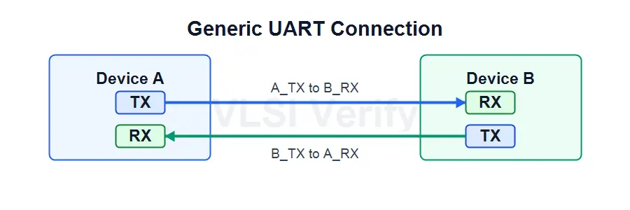
Generic UART Connection
A basic full-duplex UART connection is simple: each device’s TX pin connects to the other device’s RX pin.
| Signal | Direction | Purpose |
|---|---|---|
| TX | Output | Serial transmit data |
| RX | Input | Serial receive data |
Note: TX connects to the other side’s RX. Connecting TX-to-TX and RX-to-RX is a common wiring mistake.
UART, USART, RS-232, SPI, and I2C
UART describes the asynchronous transmit/receive function and frame timing. It does not, by itself, define a board connector or a universal voltage standard.
| Interface | Clock line? | Typical wires | Addressing | Duplex | Main idea |
|---|---|---|---|---|---|
| UART | No | TX, RX, GND | No | Full duplex with separate TX/RX | Asynchronous serial character frames |
| USART | Optional | Depends on mode | No | Depends on mode | UART-like async plus possible synchronous modes |
| SPI | Yes | SCLK, MOSI, MISO, CS | Chip-select based | Full duplex | Synchronous controller/peripheral shifting |
| I2C | Yes, shared | SCL, SDA, GND | Yes | Half duplex | Multi-drop two-wire bus |
| RS-232 | No separate clock | TX, RX, GND/control | No | Usually full duplex | Physical/electrical serial interface often carrying UART-style frames |
UART vs RS-232: UART-level signals are commonly logic-level signals inside a board or chip. RS-232 is a physical/electrical interface with different voltage levels and inverted signaling relative to many logic-level UART connections. A transceiver is normally used between logic-level UART pins and an RS-232 connector.
UART Protocol