Tutorials
Protocols
Learn More
SPI Architecture
SPI architecture is built around one simple idea: a controller selects one peripheral, provides a clock, and both sides shift data bit by bit. Unlike I2C, SPI does not use an address field on the bus to choose a device. Device selection is normally done outside the data stream using a dedicated chip-select signal.
At a high level, an SPI system has three parts:
| Part | Role |
|---|---|
| Controller | Starts the transfer, drives SCLK, drives MOSI, and controls CS. |
| Peripheral | Responds only when selected, samples MOSI, and drives MISO. |
| Bus signals | Carry clock, data, and selection information between controller and peripheral. |
The controller is the timing owner. It decides when the transaction starts, how fast the clock runs, which clock edge is used for sampling, how many bits are transferred, and when the selected peripheral is released.
The peripheral is mostly reactive. It waits for CS to become active, follows the incoming SCLK, samples incoming bits on MOSI, and returns outgoing bits on MISO if the transaction requires read data.
The easiest mental model is a pair of shift registers. On every SPI clock cycle, one bit moves from the controller to the peripheral on MOSI, and one bit can move from the peripheral to the controller on MISO.
Single Peripheral
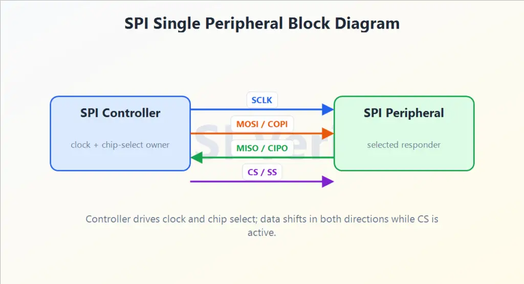
In a single-peripheral system, the controller directly connects to one SPI device. This is the cleanest topology and is common for simple sensors, small converters, and point-to-point peripheral links.
For a beginner, this is the best architecture to study first:
- SCLK tells both sides when each bit position occurs.
- MOSI carries controller-to-peripheral information such as commands or write data.
- MISO carries peripheral-to-controller information such as read data or status.
- CS defines the active transaction window.
When CS is inactive, the peripheral should ignore the SPI clock and data lines for that transaction. When CS becomes active, the peripheral treats the next clock edges as meaningful.
Multiple Peripherals
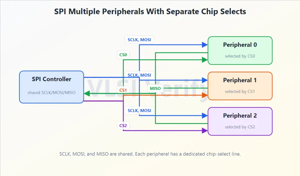
In the common multi-peripheral topology, SCLK, MOSI, and MISO are shared. Each peripheral gets a separate chip-select line.
Only one peripheral is normally selected at a time. The controller activates CS0 to talk to peripheral 0, CS1 to talk to peripheral 1, and so on. This makes SPI simple because the bus does not need an address phase.
Key rule: only the selected peripheral should drive MISO. If two peripherals drive MISO at the same time, the data can corrupt and the board can see contention.
Full-Duplex Idea
SPI sends and receives at the same time. Every clock edge moves data forward:
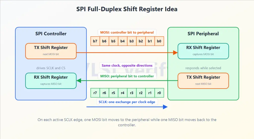
Even when the controller only wants to read, it still sends dummy bits because it must generate clock pulses for the peripheral to return data.
This is an important SPI concept: a “read” is still a clocked exchange. The controller may not care about the dummy data it sends on MOSI, but the peripheral needs those clock edges to shift useful data back on MISO.
SPI Protocol