Tutorials
Protocols
Learn More
Transaction Flow
An SPI transaction is the complete communication window between one controller and one selected peripheral. In most systems, the transaction begins when the controller asserts CS/SS, continues while the controller toggles SCLK, and ends when the controller stops the clock and deasserts CS/SS.
The important idea is this: SPI is clock-driven, not message-driven. The peripheral does not independently send a response whenever it wants. The controller must keep generating clock cycles, and on every clock cycle both sides can shift one bit. The controller sends one bit on MOSI, the peripheral sends one bit on MISO, and both sides sample according to the selected SPI mode.
SPI does not define one universal packet format. The bus defines the signal behavior; the peripheral datasheet defines the meaning of the clocked bits. Those bits may represent command, address, dummy, status, or data fields.
Transaction Vocabulary
| Term | Simple Meaning |
|---|---|
| Bit | One value shifted on MOSI or MISO during a clock cycle |
| Word | A group of bits shifted as a unit, commonly 8 bits but not always |
| Transfer | One continuous clocked movement of one or more words |
| Transaction | The complete selected operation framed by CS/SS |
| Dummy bits | Bits sent mainly to create clock cycles for receiving data |
| Phase | A logical part of a transaction, such as command, address, dummy, or data |
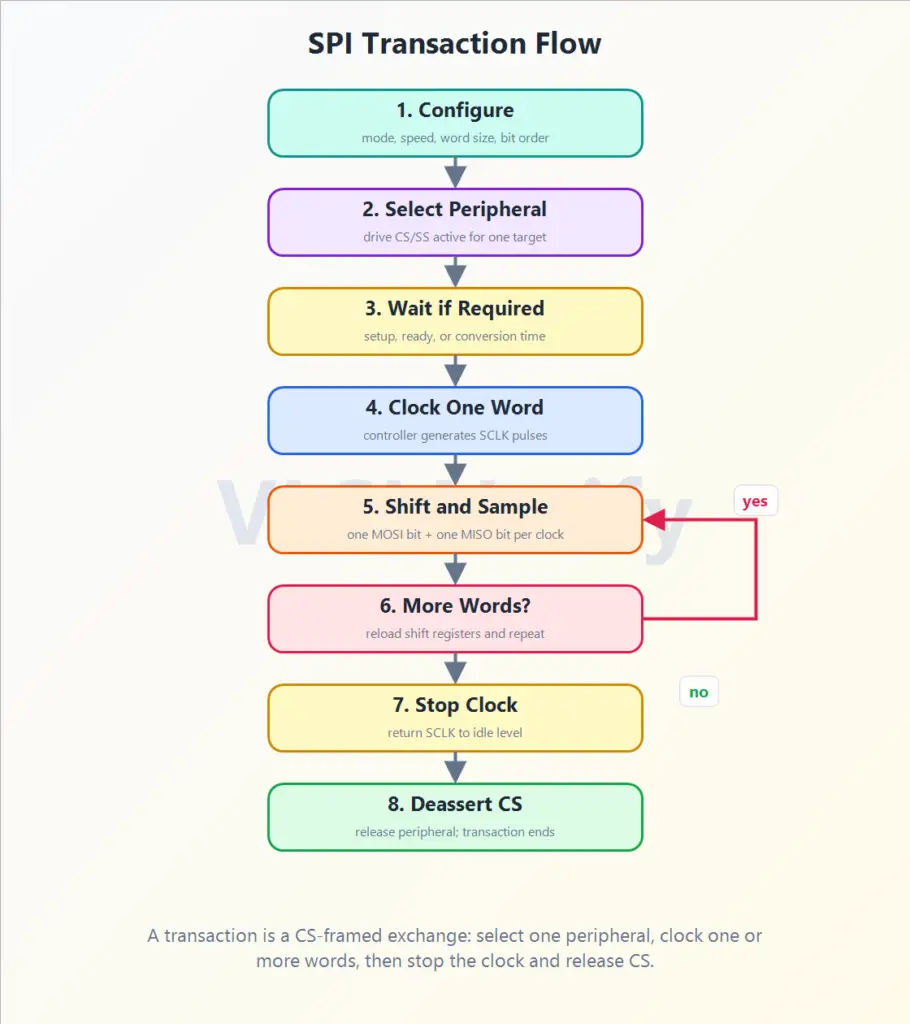
Transaction Flow Diagram
The transaction flow diagram shows the controller-side view of one complete SPI operation. Read it from top to bottom: configure the transfer, select one peripheral, wait if the device requires setup or ready time, clock one word, shift and sample bits, repeat for more words if needed, stop the clock, and release CS/SS.
The More Words? step matters because many SPI operations are multi-byte. For example, a read from a memory-like peripheral may require a command byte, address bytes, dummy clocks, and then returned data, all while CS/SS remains active.
Step-by-Step Flow
| Step | What Happens | Why It Matters |
|---|---|---|
| 1. Configure | Controller sets mode, clock speed, word size, bit order, and target peripheral | The controller and peripheral must agree on timing before bits are exchanged |
| 2. Select peripheral | Controller drives CS/SS active for one peripheral | Only the selected peripheral should respond and drive MISO |
| 3. Wait if required | Controller waits before clocking if the device needs setup, ready, or conversion time | Some peripherals need time after selection before valid clocking begins |
| 4. Clock one word | Controller generates the required SCLK pulses for one word | No clock means no SPI data movement |
| 5. Shift and sample | One bit moves on MOSI and one bit moves on MISO during each clock cycle | This is the full-duplex heart of SPI |
| 6. More words? | Controller reloads/continues shifting if the transaction has more command, address, dummy, or data words | Multi-byte transactions remain inside the same selected window when required |
| 7. Stop clock | Controller stops toggling SCLK and returns it to the idle level | The clocked portion of the exchange is complete |
| 8. Deassert CS | Controller releases the peripheral | The transaction ends; many peripherals latch, commit, or reset parser state here |
What Happens Inside One Clocked Word?
During a clocked word, both devices behave like linked shift registers:
- The controller places or shifts the next output bit onto MOSI.
- The peripheral places or shifts the next output bit onto MISO.
- On the configured sampling edge, both sides capture the incoming bit.
- The bit counter advances.
- The process repeats until the word is complete.
After one word is complete, the controller may stop or continue with another word. If more data needs to be exchanged, both sides conceptually reload or continue their shift registers, and the controller keeps generating clocks.
SPI Protocol