Tutorials
Protocols
Learn More
SPI Modes
SPI modes define the clock idle level and the clock edge used for sampling data. A controller and peripheral must use the same SPI mode; otherwise, the waveform may look active but the received bits can be wrong.
Two settings create the four common SPI modes:
| Parameter | Meaning |
|---|---|
| CPOL | Clock idle level |
| CPHA | Which clock edge samples data |
Common Modes
The four common SPI modes are:
| Mode | CPOL | CPHA | Clock Idle | Data Sampled On |
|---|---|---|---|---|
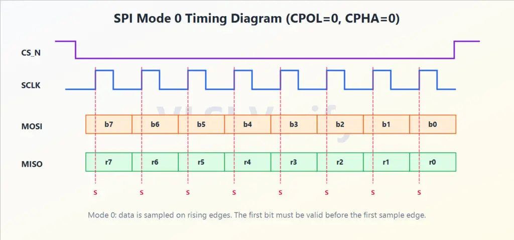
| 0 | 0 | 0 | Low | Rising edge |
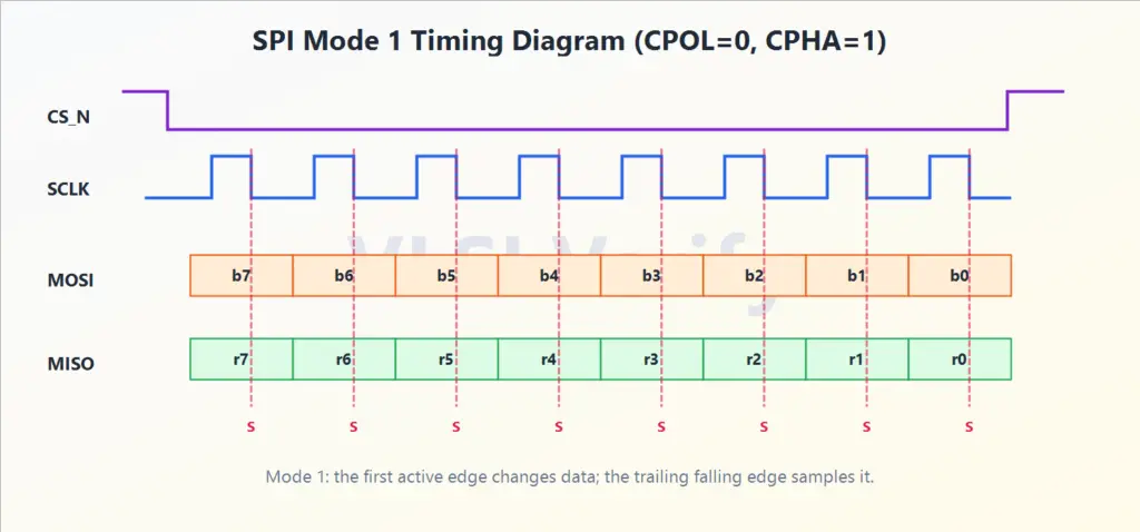
| 1 | 0 | 1 | Low | Falling edge |
| 2 | 1 | 0 | High | Falling edge |
| 3 | 1 | 1 | High | Rising edge |
Wrong mode is one of the most common SPI mistakes. The transaction may still show clocks and data on a waveform, but the receiver samples each bit on the wrong edge.
During a transaction, the selected mode tells each side exactly when to sample incoming data and when to change outgoing data. For CPHA=0, the first data bit must be valid as soon as the selected transaction begins because the first active clock edge is a sample edge. For CPHA=1, the first active edge is used to launch or change data, and the next edge samples it.
This is why SPI mode must be configured before asserting CS/SS.
Mode 0 example:
Mode 1 example:
Chip Select (CS/SS) Framing
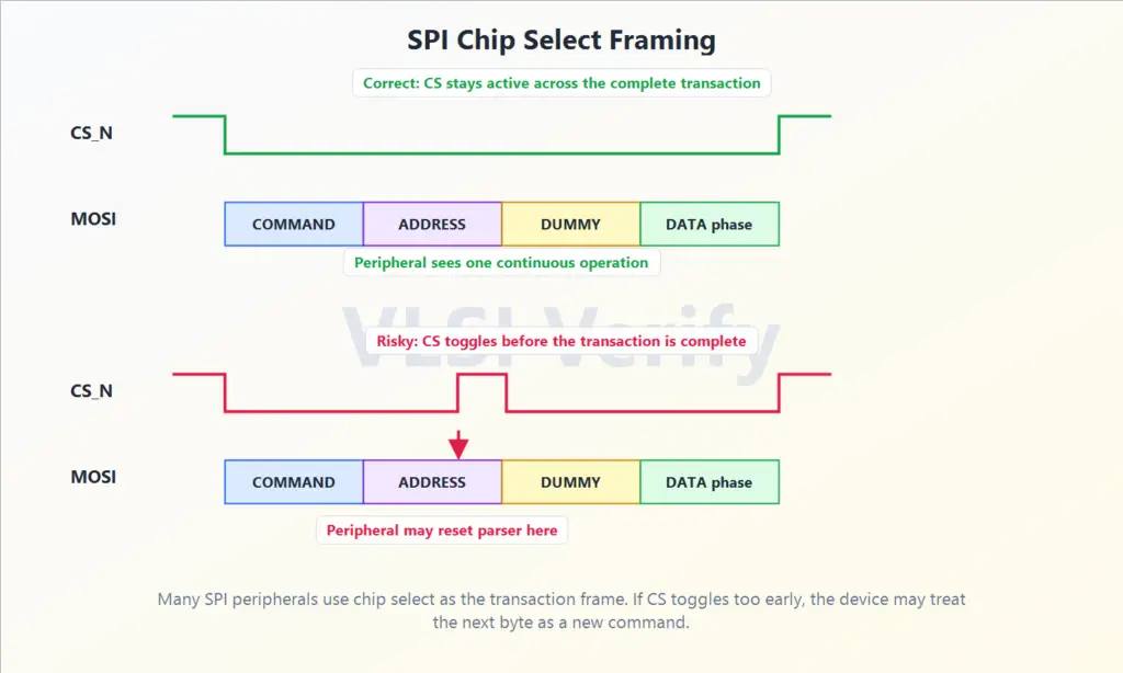
CS/SS is more than a simple enable signal. It selects one peripheral and often defines the transaction boundary. While CS/SS is active, the selected peripheral treats SCLK, MOSI, and MISO activity as part of the current operation. When CS/SS becomes inactive, many peripherals finish, latch, commit, or reset their internal command state.
Most SPI devices use active-low chip select, often written as CS_N, SS_N, nCS, or nSS. That means the peripheral is selected when the signal is low.
Typical behavior:
- Keep CS/SS inactive while the bus is idle.
- Assert CS/SS for the target peripheral.
- Send command bits.
- Send address bits if required.
- Send dummy clocks if the peripheral needs time before read data.
- Send or receive data bits.
- Stop clocking.
- Deassert CS/SS.
Some peripherals require CS/SS to stay active across the entire command, address, dummy, and data sequence. If CS/SS toggles too early, the peripheral may treat the next byte as a new command instead of continuing the old one.
In a multi-peripheral SPI bus, the controller should normally assert only one chip-select line at a time. This prevents two peripherals from responding together or driving the shared MISO line at the same time.
SPI Protocol