Tutorials
Learn More
Asynchronous FIFO
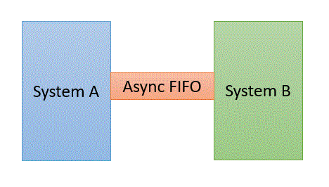
In asynchronous FIFO, data read and write operations use different clock frequencies. Since write and read clocks are not synchronized, it is referred to as asynchronous FIFO. Usually, these are used in systems where data need to pass from one clock domain to another which is generally termed as ‘clock domain crossing’. Thus, asynchronous FIFO helps to synchronize data flow between two systems working on different clocks.

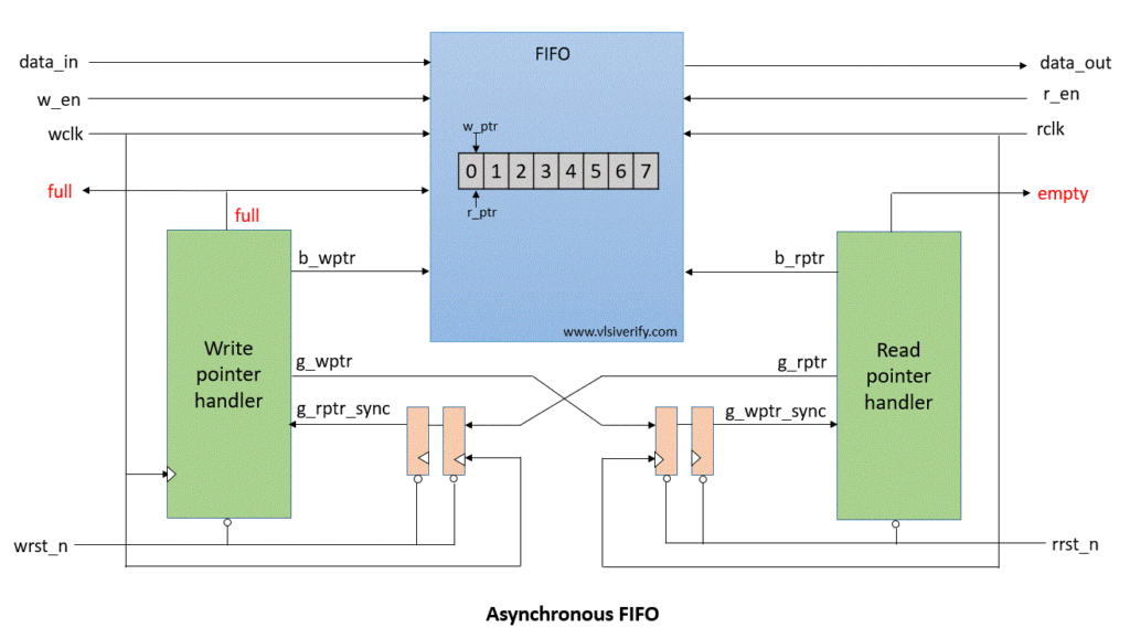
Asynchronous FIFO Block Diagram

Signals:
wr_en: write enable
wr_data: write data
full: FIFO is full
empty: FIFO is empty
rd_en: read enable
rd_data: read data
b_wptr: binary write pointer
g_wptr: gray write pointer
b_wptr_next: binary write pointer next
g_wptr_next: gray write pointer next
b_rptr: binary read pointer
g_rptr: gray read pointer
b_rptr_next: binary read pointer next
g_rptr_next: gray read pointer next
b_rptr_sync: binary read pointer synchronized
b_wptr_sync: binary write pointer synchronized
Asynchronous FIFO Operation
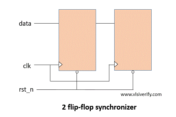
In the case of synchronous FIFO, the write and read pointers are generated on the same clock. However, in the case of asynchronous FIFO write pointer is aligned to the write clock domain whereas the read pointer is aligned to the read clock domain. Hence, it requires domain crossing to calculate FIFO full and empty conditions. This causes metastability in the actual design. In order to resolve this metastability, 2 flip flops or 3 flip flops synchronizer can be used to pass write and read pointers. For explanation, we will go with 2 flip-flop synchronizers. Please note that a single “2 FF synchronizer” can resolve metastability for only one bit. Hence, depending on write and read pointers multiple 2FF synchronizers are required.

module synchronizer #(parameter WIDTH=3) (input clk, rst_n, [WIDTH:0] d_in, output reg [WIDTH:0] d_out);
  reg [WIDTH:0] q1;
  always@(posedge clk) begin
    if(!rst_n) begin
      q1 <= 0;
      d_out <= 0;
    end
    else begin
      q1 <= d_in;
      d_out <= q1;
    end
  end
endmodule
Usage of Binary to Gray code converter and vice-versa in Asynchronous FIFO
Till now, we discussed how to get asynchronous write and read pointers in respective clock domains. However, we should not pass binary formatted write and read pointer values. Due to metastability, the overall write or read pointer value might be different.
Example: When binary value wr_ptr = 4’b1101 at the write clock domain is transferred via 2FF synchronizer, at the read clock domain wr_ptr value may receive as 4’b1111 or any other value that is not acceptable. Whereas gray code is assured to have only a single bit change from its previous value. Hence, both write and read pointers need to convert first to their equivalent gray code in their corresponding domain and then pass them to an opposite domain. To check FIFO full and empty conditions in another domain, we have two ways.
Way 1
Convert received gray code formatted pointers to binary format and then check for the full and empty conditions.
FIFO full condition
g2b_converter g2b_wr(g_rptr_sync, b_rptr_sync);
wrap_around = b_rptr_sync[PTR_WIDTH] ^ b_wptr[PTR_WIDTH];
wfull = wrap_around & (b_wptr[PTR_WIDTH-1:0] == b_rptr_sync[PTR_WIDTH-1:0]);
FIFO empty condition
g2b_converter g2b_rd(g_wptr_sync, b_wptr_sync);
rempty = (b_wptr_sync == b_rptr_next);
Way 2
Check for full and empty conditions directly with the help of gray coded write and read pointer received. This is efficient as it does not need extra hardware for converting gray-coded write and read pointers to equivalent binary forms.
FIFO full condition
wfull = (g_wptr_next == {~g_rptr_sync[PTR_WIDTH:PTR_WIDTH-1], g_rptr_sync[PTR_WIDTH-2:0]});FIFO empty condition
rempty = (g_wptr_sync == g_rptr_next);Asynchronous FIFO Verilog Code
Write Pointer Handler
The output of synchronizer g_rptr_sync is given as an input to ‘write pointer handler’ module used to generate the FIFO full condition. The binary write pointer (b_wptr) is incremented if it satisfies (w_en & !full) condition. This b_wptr value is fed to the fifo_mem module to write data into the FIFO.
module wptr_handler #(parameter PTR_WIDTH=3) (
  input wclk, wrst_n, w_en,
  input [PTR_WIDTH:0] g_rptr_sync,
  output reg [PTR_WIDTH:0] b_wptr, g_wptr,
  output reg full
);

  reg [PTR_WIDTH:0] b_wptr_next;
  reg [PTR_WIDTH:0] g_wptr_next;

  reg wrap_around;
  wire wfull;

  assign b_wptr_next = b_wptr+(w_en & !full);
  assign g_wptr_next = (b_wptr_next >>1)^b_wptr_next;

  always@(posedge wclk or negedge wrst_n) begin
    if(!wrst_n) begin
      b_wptr <= 0; // set default value
      g_wptr <= 0;
    end
    else begin
      b_wptr <= b_wptr_next; // incr binary write pointer
      g_wptr <= g_wptr_next; // incr gray write pointer
    end
  end

  always@(posedge wclk or negedge wrst_n) begin
    if(!wrst_n) full <= 0;
    else        full <= wfull;
  end

  assign wfull = (g_wptr_next == {~g_rptr_sync[PTR_WIDTH:PTR_WIDTH-1], g_rptr_sync[PTR_WIDTH-2:0]});

endmodule
Read Pointer Handler
The output of synchronizer g_wptr_sync is given as an input to the ‘read pointer handler’ module to generate FIFO empty condition. The binary read pointer (b_rptr) is incremented if it satisfies (r_en & !empty) condition. This b_rptr value is fed to the fifo_mem module to read data from the FIFO.
module rptr_handler #(parameter PTR_WIDTH=3) (
  input rclk, rrst_n, r_en,
  input [PTR_WIDTH:0] g_wptr_sync,
  output reg [PTR_WIDTH:0] b_rptr, g_rptr,
  output reg empty
);

  reg [PTR_WIDTH:0] b_rptr_next;
  reg [PTR_WIDTH:0] g_rptr_next;

  assign b_rptr_next = b_rptr+(r_en & !empty);
  assign g_rptr_next = (b_rptr_next >>1)^b_rptr_next;
  assign rempty = (g_wptr_sync == g_rptr_next);

  always@(posedge rclk or negedge rrst_n) begin
    if(!rrst_n) begin
      b_rptr <= 0;
      g_rptr <= 0;
    end
    else begin
      b_rptr <= b_rptr_next;
      g_rptr <= g_rptr_next;
    end
  end

  always@(posedge rclk or negedge rrst_n) begin
    if(!rrst_n) empty <= 1;
    else        empty <= rempty;
  end
endmodule
FIFO Memory
Based on binary coded write and read pointers data is written into the FIFO or read from the FIFO respectively.
module fifo_mem #(parameter DEPTH=8, DATA_WIDTH=8, PTR_WIDTH=3) (
  input wclk, w_en, rclk, r_en,
  input [PTR_WIDTH:0] b_wptr, b_rptr,
  input [DATA_WIDTH-1:0] data_in,
  input full, empty,
  output reg [DATA_WIDTH-1:0] data_out
);
  reg [DATA_WIDTH-1:0] fifo[0:DEPTH-1];

  always@(posedge wclk) begin
    if(w_en & !full) begin
      fifo[b_wptr[PTR_WIDTH-1:0]] <= data_in;
    end
  end
  /*
  always@(posedge rclk) begin
    if(r_en & !empty) begin
      data_out <= fifo[b_rptr[PTR_WIDTH-1:0]];
    end
  end
  */
  assign data_out = fifo[b_rptr[PTR_WIDTH-1:0]];
endmodule
Top Module
`include "synchronizer.v"
`include "wptr_handler.v"
`include "rptr_handler.v"
`include "fifo_mem.v"

module asynchronous_fifo #(parameter DEPTH=8, DATA_WIDTH=8) (
  input wclk, wrst_n,
  input rclk, rrst_n,
  input w_en, r_en,
  input [DATA_WIDTH-1:0] data_in,
  output reg [DATA_WIDTH-1:0] data_out,
  output reg full, empty
);

  parameter PTR_WIDTH = $clog2(DEPTH);

  reg [PTR_WIDTH:0] g_wptr_sync, g_rptr_sync;
  reg [PTR_WIDTH:0] b_wptr, b_rptr;
  reg [PTR_WIDTH:0] g_wptr, g_rptr;

  wire [PTR_WIDTH-1:0] waddr, raddr;

  synchronizer #(PTR_WIDTH) sync_wptr (rclk, rrst_n, g_wptr, g_wptr_sync); //write pointer to read clock domain
  synchronizer #(PTR_WIDTH) sync_rptr (wclk, wrst_n, g_rptr, g_rptr_sync); //read pointer to write clock domain

  wptr_handler #(PTR_WIDTH) wptr_h(wclk, wrst_n, w_en,g_rptr_sync,b_wptr,g_wptr,full);
  rptr_handler #(PTR_WIDTH) rptr_h(rclk, rrst_n, r_en,g_wptr_sync,b_rptr,g_rptr,empty);
  fifo_mem fifom(wclk, w_en, rclk, r_en,b_wptr, b_rptr, data_in,full,empty, data_out);

endmodule
Testbench Code
module async_fifo_TB;

  parameter DATA_WIDTH = 8;

  wire [DATA_WIDTH-1:0] data_out;
  wire full;
  wire empty;
  reg [DATA_WIDTH-1:0] data_in;
  reg w_en, wclk, wrst_n;
  reg r_en, rclk, rrst_n;

  // Queue to push data_in
  reg [DATA_WIDTH-1:0] wdata_q[$], wdata;

  asynchronous_fifo as_fifo (wclk, wrst_n,rclk, rrst_n,w_en,r_en,data_in,data_out,full,empty);

  always #10ns wclk = ~wclk;
  always #35ns rclk = ~rclk;

  initial begin
    wclk = 1'b0; wrst_n = 1'b0;
    w_en = 1'b0;
    data_in = 0;

    repeat(10) @(posedge wclk);
    wrst_n = 1'b1;

    repeat(2) begin
      for (int i=0; i<30; i++) begin
        @(posedge wclk iff !full);
        w_en = (i%2 == 0)? 1'b1 : 1'b0;
        if (w_en) begin
          data_in = $urandom;
          wdata_q.push_back(data_in);
        end
      end
      #50;
    end
  end

  initial begin
    rclk = 1'b0; rrst_n = 1'b0;
    r_en = 1'b0;

    repeat(20) @(posedge rclk);
    rrst_n = 1'b1;

    repeat(2) begin
      for (int i=0; i<30; i++) begin
        @(posedge rclk iff !empty);
        r_en = (i%2 == 0)? 1'b1 : 1'b0;
        if (r_en) begin
          wdata = wdata_q.pop_front();
          if(data_out !== wdata) $error("Time = %0t: Comparison Failed: expected wr_data = %h, rd_data = %h", $time, wdata, data_out);
          else $display("Time = %0t: Comparison Passed: wr_data = %h and rd_data = %h",$time, wdata, data_out);
        end
      end
      #50;
    end

    $finish;
  end

  initial begin
    $dumpfile("dump.vcd"); $dumpvars;
  end
endmodule
Output:
Time = 1575: Comparison Passed: wr_data = 51 and rd_data = 51
Time = 1715: Comparison Passed: wr_data = cd and rd_data = cd
Time = 1855: Comparison Passed: wr_data = 0e and rd_data = 0e
Time = 1995: Comparison Passed: wr_data = db and rd_data = db
Time = 2135: Comparison Passed: wr_data = 71 and rd_data = 71
Time = 2275: Comparison Passed: wr_data = 63 and rd_data = 63
Time = 2415: Comparison Passed: wr_data = e9 and rd_data = e9
Time = 2555: Comparison Passed: wr_data = 98 and rd_data = 98
Time = 2695: Comparison Passed: wr_data = 03 and rd_data = 03
Time = 2835: Comparison Passed: wr_data = a4 and rd_data = a4
Time = 2975: Comparison Passed: wr_data = a7 and rd_data = a7
Time = 3115: Comparison Passed: wr_data = 45 and rd_data = 45
Time = 3255: Comparison Passed: wr_data = 00 and rd_data = 00
Time = 3395: Comparison Passed: wr_data = 4f and rd_data = 4f
Time = 3535: Comparison Passed: wr_data = 3e and rd_data = 3e
Time = 3675: Comparison Passed: wr_data = e7 and rd_data = e7
Time = 3815: Comparison Passed: wr_data = d8 and rd_data = d8
Time = 3955: Comparison Passed: wr_data = 31 and rd_data = 31
Time = 4095: Comparison Passed: wr_data = 8b and rd_data = 8b
Time = 4235: Comparison Passed: wr_data = 07 and rd_data = 07
Time = 4375: Comparison Passed: wr_data = a1 and rd_data = a1
Time = 4515: Comparison Passed: wr_data = 15 and rd_data = 15
Time = 4655: Comparison Passed: wr_data = e6 and rd_data = e6
Time = 4795: Comparison Passed: wr_data = 80 and rd_data = 80
Time = 4935: Comparison Passed: wr_data = 01 and rd_data = 01
Time = 5075: Comparison Passed: wr_data = 72 and rd_data = 72
Time = 5215: Comparison Passed: wr_data = c8 and rd_data = c8
Time = 5355: Comparison Passed: wr_data = dc and rd_data = dc
Time = 5495: Comparison Passed: wr_data = d7 and rd_data = d7
Time = 5635: Comparison Passed: wr_data = a9 and rd_data = a9
Waveform

Verilog Codes