Tutorials
Learn More
Multiplexer
A multiplexer (MUX) is a combinational circuit that connects any one input line (out of multiple N lines) to the single output line based on its control input signal (or selection lines)
Usually, for ‘n’ selection lines, there are N = 2^n input lines.
Nomenclature: N:1 denotes it has ‘N’ input lines and one output line.
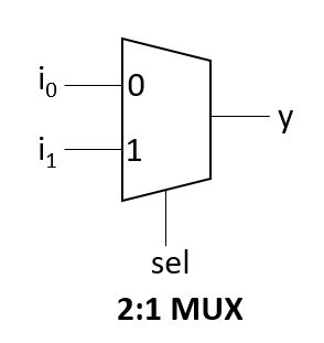
2:1 Multiplexer
2:1 MUX has 2 input lines and one select line.
Block Diagram
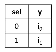
Truth Table
2:1 MUX Verilog Code
module mux_2_1(
  input sel,
  input i0, i1,
  output y);

  assign y = sel ? i1 : i0;
endmodule
Testbench Code
module mux_tb;
  reg i0, i1, sel;
  wire y;

  mux_2_1 mux(sel, i0, i1, y);
  initial begin
    $monitor("sel = %h: i0 = %h, i1 = %h --> y = %h", sel, i0, i1, y);
    i0 = 0; i1 = 1;
    sel = 0;
    #1;
    sel = 1;
  end
endmodule
Output:
sel = 0: i0 = 0, i1 = 1 --> y = 0
sel = 1: i0 = 0, i1 = 1 --> y = 1
4:1 Multiplexer
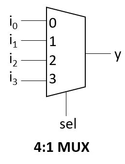
4:1 has 4 input lines and two select lines.
Block Diagram
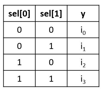
Truth Table
4:1 MUX Verilog Code
module mux_example(
  input [1:0] sel,
  input  i0,i1,i2,i3,
  output reg y);

  always @(*) begin
    case(sel)
      2'h0: y = i0;
      2'h1: y = i1;
      2'h2: y = i2;
      2'h3: y = i3;
      default: $display("Invalid sel input");
    endcase
  end
endmodule
Testbench Code
module tb;
  reg [1:0] sel;
  reg i0,i1,i2,i3;
  wire y;

  mux_example mux(sel, i0, i1, i2, i3, y);

  initial begin
    $monitor("sel = %b -> i3 = %0b, i2 = %0b ,i1 = %0b, i0 = %0b -> y = %0b", sel,i3,i2,i1,i0, y);
    {i3,i2,i1,i0} = 4'h5;
    repeat(6) begin
      sel = $random;
      #5;
    end
  end
endmodule
Output:
sel = 00 -> i3 = 0, i2 = 1 ,i1 = 0, i0 = 1 -> y = 1
sel = 01 -> i3 = 0, i2 = 1 ,i1 = 0, i0 = 1 -> y = 0
sel = 11 -> i3 = 0, i2 = 1 ,i1 = 0, i0 = 1 -> y = 0
sel = 01 -> i3 = 0, i2 = 1 ,i1 = 0, i0 = 1 -> y = 0
4:1 MUX using 2:1 MUXes
Block Diagram
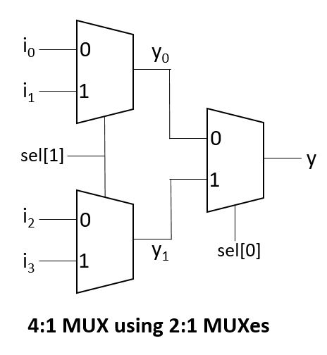
4:1 MUX using 2:1 MUXes Verilog Code
module mux_2_1(
  input sel,
  input i0, i1,
  output y);

  assign y = sel ? i1 : i0;
endmodule

module mux_4_1(
  input sel0, sel1,
  input  i0,i1,i2,i3,
  output reg y);

  wire y0, y1;

  mux_2_1 m1(sel1, i2, i3, y1);
  mux_2_1 m2(sel1, i0, i1, y0);
  mux_2_1 m3(sel0, y0, y1, y);
endmodule
Testbench Code
module tb;
  reg sel0, sel1;
  reg i0,i1,i2,i3;
  wire y;

  mux_4_1 mux(sel0, sel1, i0, i1, i2, i3, y);

  initial begin
    $monitor("sel0=%b, sel1=%b -> i3 = %0b, i2 = %0b ,i1 = %0b, i0 = %0b -> y = %0b", sel0,sel1,i3,i2,i1,i0, y);
    {i3,i2,i1,i0} = 4'h5;

    repeat(6) begin
      {sel0, sel1} = $random;
      #5;
    end
  end
endmodule
Output:
sel0=0, sel1=0 -> i3 = 0, i2 = 1 ,i1 = 0, i0 = 1 -> y = 1
sel0=0, sel1=1 -> i3 = 0, i2 = 1 ,i1 = 0, i0 = 1 -> y = 0
sel0=1, sel1=1 -> i3 = 0, i2 = 1 ,i1 = 0, i0 = 1 -> y = 0
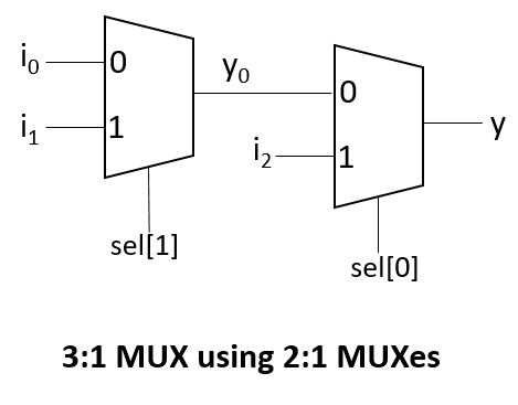
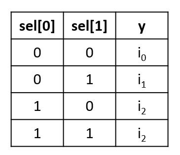
sel0=0, sel1=1 -> i3 = 0, i2 = 1 ,i1 = 0, i0 = 1 -> y = 03:1 Multiplexer
In 3:1 MUX, for two select inputs (sel = 2’b01 and sel = 2’b11), same input (i2) will be driven to the output y.
Block Diagram
Truth Table
3:1 MUX Verilog Code
module mux_2_1(
  input sel,
  input i0, i1,
  output y);

  assign y = sel ? i1 : i0;
endmodule

module mux_3_1(
  input sel0, sel1,
  input  i0,i1,i2,i3,
  output reg y);

  wire y0, y1;

  mux_2_1 m1(sel1, i0, i1, y0);
  mux_2_1 m2(sel0, y0, i2, y);
endmodule
Testbench Code
module tb;
  reg sel0, sel1;
  reg i0,i1,i2,i3;
  wire y;

  mux_3_1 mux(sel0, sel1, i0, i1, i2, i3, y);

  initial begin
    $monitor("sel0=%b, sel1=%b -> i3 = %0b, i2 = %0b ,i1 = %0b, i0 = %0b -> y = %0b", sel0,sel1,i3,i2,i1,i0, y);
    {i3,i2,i1,i0} = 4'h5;

    repeat(8) begin
      {sel0, sel1} = $random;
      #5;
    end
  end
endmodule
Output:
sel0=0, sel1=0 -> i3 = 0, i2 = 1 ,i1 = 0, i0 = 1 -> y = 1
sel0=0, sel1=1 -> i3 = 0, i2 = 1 ,i1 = 0, i0 = 1 -> y = 0
sel0=1, sel1=1 -> i3 = 0, i2 = 1 ,i1 = 0, i0 = 1 -> y = 1
sel0=0, sel1=1 -> i3 = 0, i2 = 1 ,i1 = 0, i0 = 1 -> y = 0
sel0=1, sel1=0 -> i3 = 0, i2 = 1 ,i1 = 0, i0 = 1 -> y = 1
Verilog Codes