Tutorials
Protocols
Learn More
SR Flip Flop
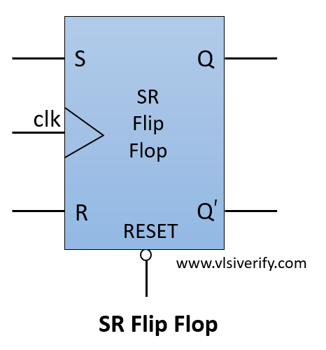
The SR flip flop has two inputs SET ‘S’ and RESET ‘R’. As the name suggests, when S = 1, output Q becomes 1, and when R = 1, output Q becomes 0. The output Q’ is the complement of Q.
Block Diagram
Truth Table
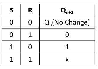
For S = 1 and R = 1, output Q = x i.e. 1 or 0. Hence, S=1 and R=1 input combination is invalid and must be avoided in the SR flip flop.
SR Flip Flop Verilog Code
module SR_flipflop (
  input clk, rst_n,
  input s,r,
  output reg q,
  output q_bar
  );

  // always@(posedge clk or negedge rst_n) // for asynchronous reset
  always@(posedge clk) begin // for synchronous reset
    if(!rst_n) q <= 0;
    else begin
      case({s,r})
        2'b00: q <= q;    // No change
        2'b01: q <= 1'b0; // reset
        2'b10: q <= 1'b1; // set
        2'b11: q <= 1'bx; // Invalid inputs
      endcase
    end
  end
  assign q_bar = ~q;
endmodule
Testbench Code
module tb;
  reg clk, rst_n;
  reg s, r;
  wire q, q_bar;

  SR_flipflop dff(clk, rst_n, s, r, q, q_bar);

  always #2 clk = ~clk;
  initial begin
    clk = 0; rst_n = 0;
    $display("Reset=%b --> q=%b, q_bar=%b", rst_n, q, q_bar);
    #3 rst_n = 1;
    $display("Reset=%b --> q=%b, q_bar=%b", rst_n, q, q_bar);

    drive(2'b00);
    drive(2'b01);
    drive(2'b10);
    drive(2'b11);
    #5;
    $finish;
  end

  task drive(bit [1:0] ip);
    @(posedge clk);
    {s,r} = ip;
    #1 $display("s=%b, r=%b --> q=%b, q_bar=%b",s, r, q, q_bar);
  endtask

  initial begin
    $dumpfile("dump.vcd");
    $dumpvars(1);
  end
endmodule
Output:
Reset=0 --> q=x, q_bar=x
Reset=1 --> q=0, q_bar=1
s=0, r=0 --> q=0, q_bar=1
s=0, r=1 --> q=0, q_bar=1
s=1, r=0 --> q=1, q_bar=0
s=1, r=1 --> q=x, q_bar=x
Verilog Codes