Tutorials
Learn More
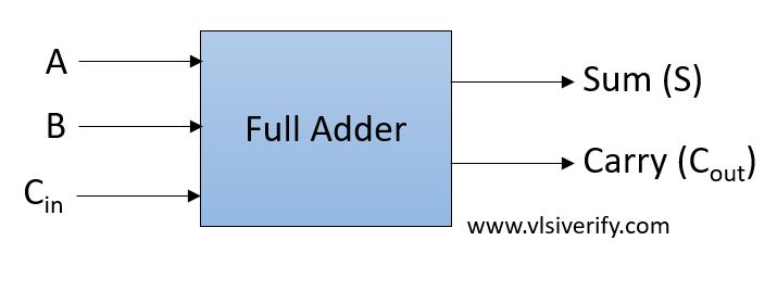
Full Adder
The full adder adds three single-bit input and produce two single-bit output. Thus, it is useful when an extra carry bit is available from the previously generated result.
Block Diagram
Truth Table
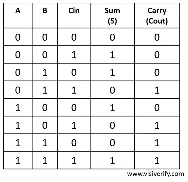
Output:
S = A ^ B ^ Cin
Cout = A·B + B·Cin + A·Cin
Full Adder Verilog Code
module full_adder(input a, b, cin, output S, Cout);
  assign S = a ^ b ^ cin;
  assign Cout = (a & b) | (b & cin) | (a & cin);
endmodule
Testbench Code
module tb_top;
  reg a, b, c;
  wire s, c_out;

  full_adder fa(a, b, c, s, c_out);

  initial begin
    $monitor("At time %0t: a=%b b=%b, cin=%b, sum=%b, carry=%b",$time, a,b,c,s,c_out);
    a = 0; b = 0; c = 0; #1;
    a = 0; b = 0; c = 1; #1;
    a = 0; b = 1; c = 0; #1;
    a = 0; b = 1; c = 1; #1;
    a = 1; b = 0; c = 0; #1;
    a = 1; b = 0; c = 1; #1;
    a = 1; b = 1; c = 0; #1;
    a = 1; b = 1; c = 1;
  end
endmodule
Output:
At time 0: a=0 b=0, cin=0, sum=0, carry=0
At time 1: a=0 b=0, cin=1, sum=1, carry=0
At time 2: a=0 b=1, cin=0, sum=1, carry=0
At time 3: a=0 b=1, cin=1, sum=0, carry=1
At time 4: a=1 b=0, cin=0, sum=1, carry=0
At time 5: a=1 b=0, cin=1, sum=0, carry=1
At time 6: a=1 b=1, cin=0, sum=0, carry=1
At time 7: a=1 b=1, cin=1, sum=1, carry=1
However, full adder can also be designed using two half adders.
Full Adder using Half Adder Verilog Code
module half_addr(input a, b, output s, c);
  assign s = a^b;
  assign c = a & b;
endmodule

module full_adder(input a, b, cin, output s_out, c_out);
  wire s, c0, c1;
  half_addr HA1 (a, b, s, c0);
  half_addr HA2 (s, cin, s_out, c1);

  assign c_out = c0 | c1;
endmodule
Output:
At time 0: a=0 b=0, cin=0, sum=0, carry=0
At time 1: a=0 b=0, cin=1, sum=1, carry=0
At time 2: a=0 b=1, cin=0, sum=1, carry=0
At time 3: a=0 b=1, cin=1, sum=0, carry=1
At time 4: a=1 b=0, cin=0, sum=1, carry=0
At time 5: a=1 b=0, cin=1, sum=0, carry=1
At time 6: a=1 b=1, cin=0, sum=0, carry=1
At time 7: a=1 b=1, cin=1, sum=1, carry=1
Verilog Codes