Tutorials
Learn More
Full Subtractor
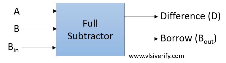
A full subtractor is designed to accommodate the extra borrow bit from the previous stage. Thus it has three single-bit inputs and produces two single-bit outputs.
Block Diagram
Truth Table
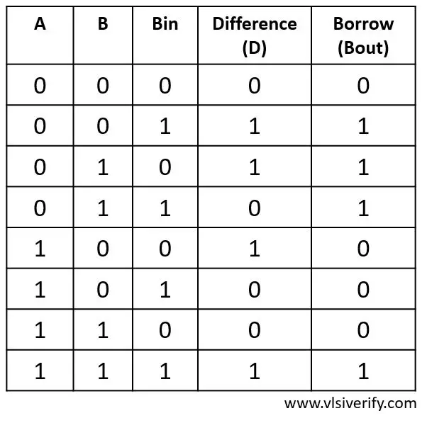
Output
D = A ^ B ^ Bin
Bout = A’ · B + (A ^ B)’ · Bin
Full Subtractor Verilog Code
module full_subtractor(input a, b, Bin, output D, Bout);
  assign D = a ^ b ^ Bin;
  assign Bout = (~a & b) | (~(a ^ b) & Bin);
endmodule
Testbench Code
module tb_top;
  reg a, b, Bin;
  wire D, Bout;

  full_subtractor fs(a, b, Bin, D, Bout);

initial begin
  $monitor("At time %0t: a=%b b=%b, Bin=%b, difference=%b, borrow=%b",$time, a,b,Bin,D,Bout);
    a = 0; b = 0; Bin = 0; #1;
    a = 0; b = 0; Bin = 1; #1;
    a = 0; b = 1; Bin = 0; #1;
    a = 0; b = 1; Bin = 1; #1;
    a = 1; b = 0; Bin = 0; #1;
    a = 1; b = 0; Bin = 1; #1;
    a = 1; b = 1; Bin = 0; #1;
    a = 1; b = 1; Bin = 1;
  end
endmodule
Output:
At time 0: a=0 b=0, Bin=0, difference=0, borrow=0
At time 1: a=0 b=0, Bin=1, difference=1, borrow=1
At time 2: a=0 b=1, Bin=0, difference=1, borrow=1
At time 3: a=0 b=1, Bin=1, difference=0, borrow=1
At time 4: a=1 b=0, Bin=0, difference=1, borrow=0
At time 5: a=1 b=0, Bin=1, difference=0, borrow=0
At time 6: a=1 b=1, Bin=0, difference=0, borrow=0
At time 7: a=1 b=1, Bin=1, difference=1, borrow=1
Verilog Codes