Write and read data
The data channels carry the payload described by the transaction request. The request says how many transfers are expected and how wide each transfer is allowed to be. The data channels then move those transfers using their own handshake.
Write and read data use the same configured data width. In the specification, the DATA_WIDTH property applies to both WDATA and RDATA, and legal interface widths range from 8 bits to 1024 bits. AxSIZE can describe a transfer smaller than the data bus width, which is why byte lanes and strobes matter.
| Aspect | Write data channel W | Read data channel R |
|---|---|---|
| Direction | Manager to Subordinate | Subordinate to Manager |
| Payload | WDATA plus byte-valid information in WSTRB | RDATA plus response information in RRESP |
| Beat count | Determined by AWLEN + 1 | Determined by ARLEN + 1 |
| Final beat | WLAST on the final write data transfer | RLAST on the final read data transfer |
| ID handling | No WID; data association is controlled by write ordering rules | RID identifies the read request being completed |
| Response | Separate B channel after write completion | Response rides with every R transfer |
The most important difference is response placement. A write transaction has one response on the B channel after the write request and final write data transfer have been accepted. A read transaction has no separate response-only channel; every read data beat carries its own RRESP.
Write data channel (W)
The W channel is driven by the Manager. It carries the write data transfers that belong to a write request. The number of W transfers must match the Length described by the AW request. If AWLEN = 3, the Manager must provide four write data transfers.
WLAST identifies the final write data transfer of the transaction. The Manager must assert WLAST while it is driving that final transfer. Earlier write data transfers have WLAST LOW. A Subordinate that does not use WLAST can omit it by interface property, but in a normal tutorial view it is useful because it makes the end of the write burst visible.
WDATA carries the data bus value. For inactive byte lanes, it is recommended to drive WDATA to zero. The receiving Subordinate must use WSTRB, not just the visual value on WDATA, to decide which bytes are valid for the write.
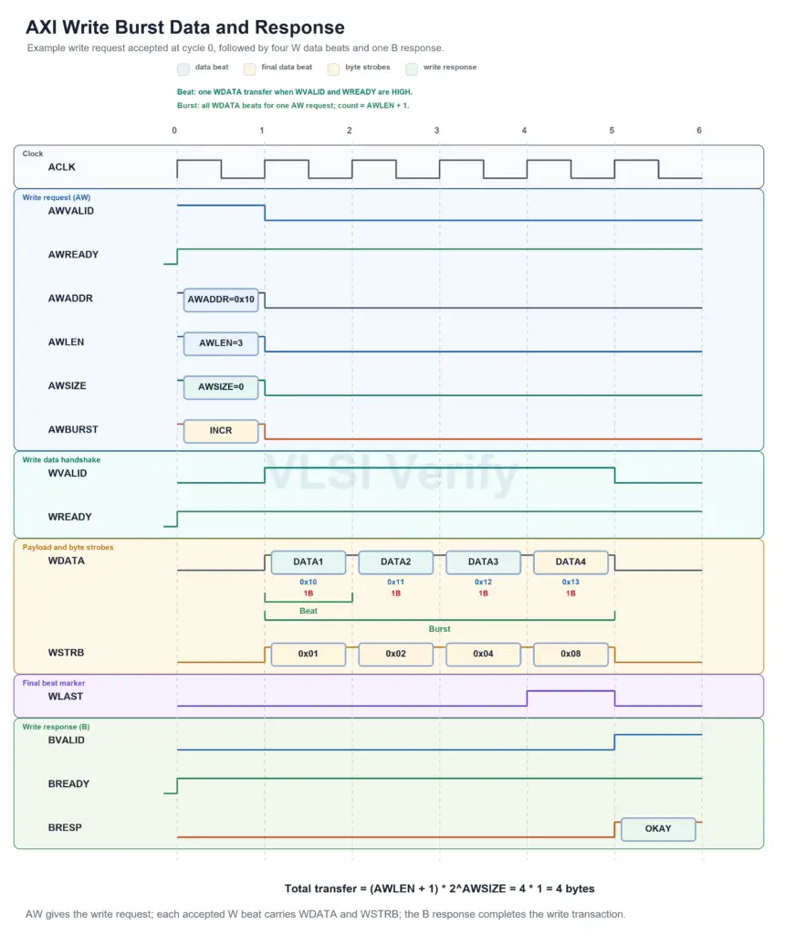
The waveform shows a complete four-beat write burst. The write request is accepted first: AWADDR = 0x10, AWLEN = 3, AWSIZE = 0, and AWBURST = INCR. Because AWLEN stores the number of transfers minus one, AWLEN = 3 means four write data beats. Because AWSIZE = 0, each beat transfers 2^0 = 1 byte.
After the request, each cycle where WVALID and WREADY are HIGH accepts one WDATA beat. The beat address annotations show the byte addresses 0x10, 0x11, 0x12, and 0x13. The WSTRB values select the active byte lane for each accepted beat, and WLAST is asserted with DATA4 to mark the final beat of the burst. The write response is separate from the data beats: after the request and final data beat are accepted, the Subordinate returns BRESP = OKAY on the B channel.
So, for this example:
| Field | Value | Meaning |
|---|---|---|
AWLEN | 3 | AWLEN + 1 = 4 data beats |
AWSIZE | 0 | 2^AWSIZE = 1 byte per beat |
AWBURST | INCR | Address advances by one byte per beat |
| Total transfer | 4 * 1 | 4 bytes |
Write strobes
WSTRB carries one strobe bit for each 8-bit byte lane of WDATA. WSTRB[n] corresponds to WDATA[(8*n)+7 : (8*n)]. A strobe bit HIGH means the byte lane contains valid write data for that transfer.
When WVALID is HIGH:
WSTRBbits for bytes outside the legal transfer window must be LOW.WSTRBbits inside the legal transfer window indicate which bytes are actually written.- For transactions where all byte lanes are required, the relevant strobes must be asserted.
- If all legal
WSTRBbits are LOW, that write data transfer writes no bytes, but the transfer still counts toward Length.
When WVALID is LOW, write data and strobes are not being transferred. WSTRB can take any value, although driving it LOW or holding its previous value is usually cleaner for implementation and debug.
If a Manager only issues transactions where all write strobes are asserted, WSTRB can be omitted by interface property and tied HIGH at the attached Subordinate.
Read data channel (R)
The R channel is driven by the Subordinate in response to a read request. Even if the Subordinate has only one source of read data, it must assert RVALID only as a response to an accepted request. The number of R transfers must match the Length described by the AR request.
RID matches the ARID of the read request being completed. This is what lets a Manager have multiple read transactions outstanding and still match returned data to the correct request. If different read IDs are allowed to complete independently, the Manager must track each RID stream separately.
RDATA carries the read data value. For inactive byte lanes, it is recommended to drive RDATA to zero. A read transfer can be narrower than the data bus, so byte-lane interpretation still comes from the request address and Size.
RRESP is valid with every RVALID transfer when the signal is present. The response value does not have to be the same on every transfer of a multi-transfer read. However, all transfers described by Length must still be completed, even if one of the transfers reports an error response. For response encodings where data is not valid, the Manager must treat the associated RDATA beat carefully.
RLAST marks the final read data transfer of the transaction. It is not a response code, and it does not mean that earlier beats were response-free. It simply identifies the last R beat for that read transaction.
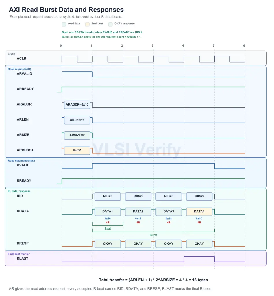
The waveform shows a four-beat read burst. The read request is accepted with ARADDR = 0x10, ARLEN = 3, ARSIZE = 2, and ARBURST = INCR. Here, ARLEN = 3 means four read data beats, and ARSIZE = 2 means each beat carries 2^2 = 4 bytes.
Each cycle where RVALID and RREADY are HIGH accepts one read data beat. The example addresses progress as 0x10, 0x14, 0x18, and 0x1C because this is an incrementing burst with four bytes per beat. RID remains the ID of the read request being completed, so the Manager can match these beats back to the correct ARID. RRESP = OKAY is shown on every beat, and RLAST is asserted only with DATA4, the final read transfer.
So, for this example:
| Field | Value | Meaning |
|---|---|---|
ARLEN | 3 | ARLEN + 1 = 4 data beats |
ARSIZE | 2 | 2^ARSIZE = 4 bytes per beat |
ARBURST | INCR | Address advances by four bytes per beat |
| Total transfer | 4 * 4 | 16 bytes |
| Read data point | Why it matters |
|---|---|
RID must match the originating ARID. | The Manager can match returned data to the correct outstanding read. |
RRESP appears on every read data transfer. | A multi-beat read can report response status per beat. |
RLAST is asserted only on the final transfer. | The Manager knows when the read transaction is complete. |
| Error response does not cancel remaining beats. | The Subordinate still completes the number of transfers described by Length. |
If RRESP_WIDTH is zero, RRESP is absent and treated as OKAY. | Some simplified interfaces can omit explicit read response signaling. |
Narrow transfers
If Size is smaller than the data bus width, the transaction uses a subset of byte lanes. This is called a narrow transfer. For example, an 8-bit transfer on a 32-bit data bus uses only one byte lane per beat, and a 32-bit transfer on a 64-bit data bus uses only four byte lanes per beat.
Narrow transfers are controlled by the request fields, not by adding a separate narrow-data channel. AxSIZE tells the maximum number of bytes in each transfer, AxADDR tells the starting byte address, and AxBURST determines how the byte-lane position changes from beat to beat.
| Burst type | Byte-lane behavior for narrow transfers |
|---|---|
INCR | The active byte lanes move as the address increments by Size. |
WRAP | The active byte lanes move like INCR, then wrap within the wrapping boundary. |
FIXED | The same byte lanes are used for every transfer in the transaction. |
For writes, WSTRB must agree with the legal byte lanes for the transfer. Byte lanes outside the allowed window must have their strobes LOW. For reads, the Subordinate returns data on the byte lanes selected by the request address and Size. In both directions, inactive byte lanes are not part of the transfer.
Narrow transfer example with 8-bit transfers
Figure shows a five-transfer transaction that starts at address 0. Each transfer is 8 bits wide, but the data channel is 32 bits wide. Because each beat transfers only one byte on a 4-byte bus, only one byte lane is active per beat.
The important point is that the active byte lane changes as the address increments. The first transfer uses the lowest byte lane, the second transfer uses the next byte lane, and so on until the fourth transfer reaches the highest byte lane of the 32-bit word. The fifth transfer then moves to the next aligned 32-bit word and again uses the lowest byte lane. The shaded cells in the specification figure are bytes that are not transferred.
This example is useful for understanding byte-lane steering. The bus is 32 bits wide, but the transfer size is only 8 bits, so the protocol must identify exactly which byte of the bus carries the addressed data for each beat.
Narrow transfer example with 32-bit transfers
Figure shows a three-transfer transaction that starts at address 4. Each transfer is 32 bits wide, and the data channel is 64 bits wide. Each beat therefore uses half of the 64-bit data bus.
Because the starting address is 4, the first transfer uses the upper 32-bit half of the 64-bit data bus. The next transfer increments to the next 32-bit address position and uses the lower 32-bit half of the next aligned 64-bit data word. The third transfer then uses the upper 32-bit half again. The active half of the bus alternates as the address advances by 4 bytes.
This example is useful because it shows that narrow transfers are not limited to single-byte accesses. A transfer can be narrow relative to the bus even when it is 32 bits wide. What matters is the relationship between AxSIZE and DATA_WIDTH.
Byte invariance
AXI uses byte-invariant data organization. Byte invariance lets big-endian and little-endian data structures coexist in memory without corrupting each other. The same addressed byte maps to the same byte lane location in memory even if software interprets multi-byte values differently.
For RTL designers, byte invariance means the byte lane is determined by address and transfer size, not by a global “swap all lanes” shortcut. Endianness conversion is a data interpretation issue; the protocol still requires correct byte-lane mapping.
AXI Protocol