Tutorials
Learn More
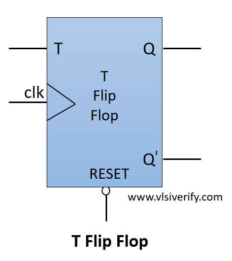
T Flip Flop
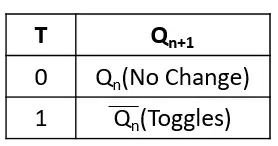
The T flip flop has single input as a ‘T’. Whenever input T=1, the output toggles from its previous state else the output remains the same as its previous state. It behaves the same as JK flip flop when J=1 and K=1. Hence, it can also be implemented by tieing both inputs (J and K) of JK flip flop.
Block Diagram
Truth Table
T Flip Flop Verilog Code
module T_flipflop (
  input clk, rst_n,
  input t,
  output reg q,
  output q_bar
  );

  // always@(posedge clk or negedge rst_n) // for asynchronous reset
  always@(posedge clk) begin // for synchronous reset
    if(!rst_n) q <= 0;
    else begin
      q <= (t?~q:q);
    end
  end
  assign q_bar = ~q;
endmodule
Testbench Code
module tb;
  reg clk, rst_n;
  reg t;
  wire q, q_bar;

  T_flipflop dff(clk, rst_n, t, q, q_bar);

  always #2 clk = ~clk;
  initial begin
    clk = 0; rst_n = 0;
    $display("Reset=%b --> q=%b, q_bar=%b", rst_n, q, q_bar);
    #3 rst_n = 1;
    $display("Reset=%b --> q=%b, q_bar=%b", rst_n, q, q_bar);

    drive(0); // Same as previous output
    drive(1); // Toggles previous output
    drive(1); // Toggles previous output
    drive(1); // Toggles previous output
    drive(0); // Same as previous output
    #5;
    $finish;
  end

  task drive(bit ip);
    @(posedge clk);
    t = ip;
    #1 $display("t=%b --> q=%b, q_bar=%b",t, q, q_bar);
  endtask

  initial begin
    $dumpfile("dump.vcd");
    $dumpvars(1);
  end
endmodule
Output:
Reset=0 --> q=x, q_bar=x
Reset=1 --> q=0, q_bar=1
t=0 --> q=0, q_bar=1
t=1 --> q=1, q_bar=0
t=1 --> q=0, q_bar=1
t=1 --> q=1, q_bar=0
t=0 --> q=1, q_bar=0
Verilog Codes