Tutorials
Protocols
Learn More
Signal Description
APB signals can be understood in groups: clock/reset, requester control, write data, completer response, optional attributes, and optional parity check signals.
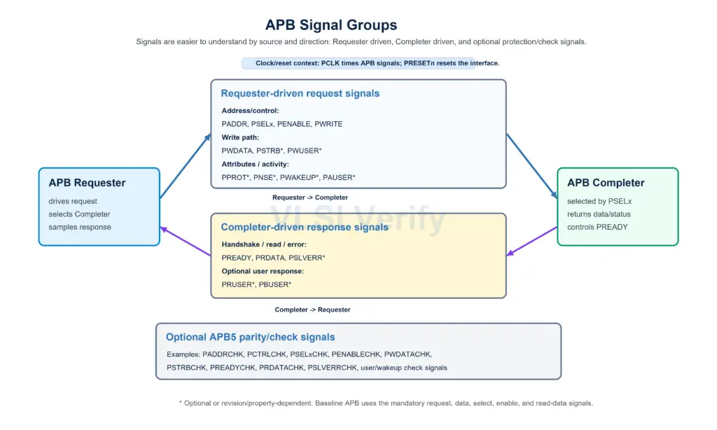
Core APB signals
| Signal | Source | Description |
|---|---|---|
| PCLK | Clock | APB clock. Protocol signals are sampled on rising edges. |
| PRESETn | Reset | Active-low reset. |
| PADDR | Requester | Address bus. It is a byte address and can be up to 32 bits wide. |
| PSELx | Requester | Select signal for a specific Completer. |
| PENABLE | Requester | Indicates Access phase, meaning the second and later cycles of a transfer. |
| PWRITE | Requester | HIGH for write transfer, LOW for read transfer. |
| PWDATA | Requester | Write data bus. Width can be 8, 16, or 32 bits. |
| PRDATA | Completer | Read data bus. Same width as PWDATA. |
Handshake and response signals
| Signal | Source | Description |
|---|---|---|
| PREADY | Completer | Extends or completes the Access phase. A transfer completes when PSELx, PENABLE, and PREADY are HIGH. |
| PSLVERR | Completer | Optional error response signal. Valid only in the final Access cycle. |
In APB2, PREADY and PSLVERR are not part of the interface. In APB3 and later, they support wait states and transfer error reporting.
Optional APB4 and APB5 signals
| Signal | Revision/use | Description |
|---|---|---|
| PSTRB | APB4+ | Write strobe. One bit per byte lane of PWDATA. |
| PPROT | APB4+ | Protection attributes: normal/privileged, secure/non-secure, data/instruction hint. |
| PNSE | APB5 RME option | Extension to protection information for Root/Realm address space support. |
| PWAKEUP | APB5 option | Wake-up indication for clock/power control logic. |
| PAUSER | APB5 user option | User-defined request attribute. |
| PWUSER | APB5 user option | User-defined write data attribute. |
| PRUSER | APB5 user option | User-defined read data attribute. |
| PBUSER | APB5 user option | User-defined response attribute. |
Address and data width
PADDR carries a byte address, not a word index. This means address value 0x04 means byte address 4 in the peripheral address map.
The APB data bus width can be 8, 16, or 32 bits. The write data bus PWDATA and read data bus PRDATA are separate physical signals, but they must have the same width on an APB interface.
For a 32-bit APB data bus, one transfer can carry 4 bytes of data:
| Data bus width | Bytes per transfer | Naturally aligned address examples |
|---|---|---|
| 8 bits | 1 byte | 0x00, 0x01, 0x02, 0x03 |
| 16 bits | 2 bytes | 0x00, 0x02, 0x04, 0x06 |
| 32 bits | 4 bytes | 0x00, 0x04, 0x08, 0x0C |
An address is aligned when it matches the transfer width boundary. For example, on a 32-bit data bus, 0x00, 0x04, and 0x08 are aligned addresses. Address 0x02 is not aligned for a 32-bit access.
The APB specification permits PADDR to be unaligned, but says the result is unpredictable. In practice, a Completer might align the address internally, use the unaligned value, return an error, or document that such access is unsupported. Because of that, RTL and software should normally use aligned addresses unless the peripheral documentation clearly says otherwise.
Even though APB has separate PWDATA and PRDATA buses, it does not perform a read and write at the same time. The transfer direction is selected by PWRITE:
| PWRITE | Transfer type | Data bus used |
|---|---|---|
| HIGH | Write | Requester drives PWDATA |
| LOW | Read | Completer drives PRDATA |
Signal validity windows
Signal validity means: when is a signal required to contain meaningful information?
Not every APB signal has to be meaningful in every clock cycle. Some signals must always be valid, some become valid when a peripheral is selected, and some are only valid when a transfer completes. This matters because RTL must sample signals only in the correct window, and assertions should not check a signal before the protocol says it is meaningful.
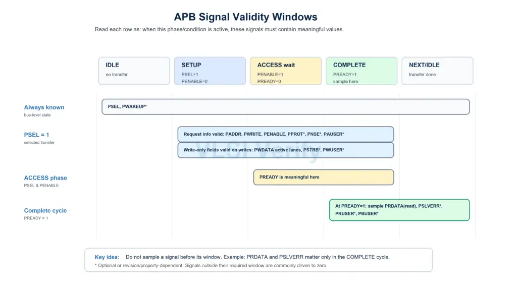
Think of APB validity in layers:
| Condition | Meaning | Signals to treat as meaningful |
|---|---|---|
| Always | Bus-level state is known even when no transfer is active | PSEL, and PWAKEUP if implemented |
| PSEL=1 | A Completer has been selected; Setup or Access is active | PADDR, PWRITE, PENABLE, PPROT, PNSE, PSTRB, request user fields, and active write data lanes |
| PSEL=1 and PENABLE=1 | Access phase is active | PREADY |
| PSEL=1, PENABLE=1, and PREADY=1 | Transfer completes in this cycle | PRDATA for reads, PSLVERR, PRUSER, and PBUSER |
For a read transfer, use PRDATA only in the cycle where the transfer finishes. That finish cycle is when PSEL, PENABLE, and PREADY are all HIGH.
Similarly, PSLVERR should not be sampled during Setup or during a wait state. It is meaningful only in the final Access cycle.
Simple verification checklist:
- PSEL must always be valid.
- PWAKEUP, if present, must always be valid.
- When PSEL is asserted, request-side address/control attributes must be valid.
- PREADY is meaningful when PSEL and PENABLE are asserted.
- PRDATA, PSLVERR, PRUSER, and PBUSER are valid only at the completed Access handshake.
- Signals that are not currently required to be valid should preferably be driven to zero where practical.
APB Protocol