Tutorials
Protocols
Learn More
Write Transfers
In a write transfer, the Requester drives the address, direction, write data, and any write-side attributes. PWRITE is HIGH. The Completer accepts the write at the completion of the Access phase.
Two types of write transfer:
• With no wait states
• With wait states
With no wait states
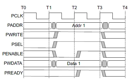
In the waveform:
- At the Setup cycle (occurs at T1), PSEL is asserted.
- PADDR, PWRITE, and PWDATA are valid.
- At the next cycle, PENABLE is asserted to start Access (at T2).
- Since PREADY is HIGH, the transfer completes at the next rising edge.
- PENABLE is deasserted after completion.
- PSEL is deasserted unless another transfer follows.
This is the shortest APB transfer: one Setup cycle and one Access cycle.
with wait states
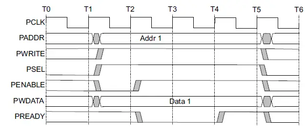
If the Completer is not ready, it drives PREADY LOW during Access. The Requester must keep the transfer stable until PREADY becomes HIGH.
During a write wait state, these signals remain unchanged:
- PADDR
- PWRITE
- PSELx
- PENABLE
- PWDATA
- PSTRB, if present
- PPROT, if present
- PAUSER, if present
- PWUSER, if present
PREADY can take any value when PENABLE is LOW that ensures that peripherals that have a fixed two cycle access can tie PREADY HIGH.
Byte write example
For a 32-bit peripheral register, a full write updates all four bytes. A sparse write updates only selected byte lanes using PSTRB. If a design does not support sparse writes, it must document the supported access types.
Example intent:
| PSTRB | Meaning on 32-bit PWDATA |
|---|---|
| 4’b1111 | Update all bytes |
| 4’b0001 | Update byte lane 0 only |
| 4’b0011 | Update byte lanes 0 and 1 |
| 4’b1100 | Update byte lanes 2 and 3 |
| 4’b0000 | No byte lane marked valid; behavior should be defined by the implementation |
Write strobes and byte lanes
PSTRB is an optional APB4/APB5 signal used for sparse writes. It marks which byte lanes of PWDATA contain valid write information.
Each PSTRB corresponds to 1 byte of the write data bus.
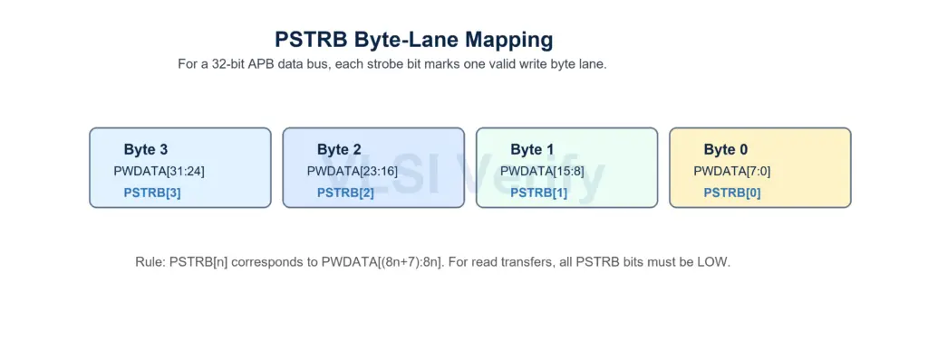
For a 32-bit data bus:
- PSTRB[0] corresponds to PWDATA[7:0]
- PSTRB[1] corresponds to PWDATA[15:8]
- PSTRB[2] corresponds to PWDATA[23:16]
- PSTRB[3] corresponds to PWDATA[31:24]
In general: PSTRB[n] corresponds to PWDATA[(8*n + 7):(8*n)]
Important PSTRB rules
- PSTRB is used only for write transfers.
- For read transfers, the Requester must drive all PSTRB bits LOW.
- If PSTRB is not present, sparse writes are not supported through that interface.
- If a Completer supports only selected access sizes or strobe patterns, that must be documented for software.
PSTRB compatibility
When connecting APB interfaces, the presence of PSTRB matters. A Requester with PSTRB can connect to a Completer without PSTRB only if sparse writes are not required. A Requester without PSTRB can connect to a Completer with PSTRB by treating all write byte lanes as valid.
This is a compatibility rule, not a performance feature. It is about preventing software and hardware from disagreeing about which bytes are updated.
APB Protocol