Gate Level Modeling
The module implementation is similar to the gate-level design description in terms of logic gates and interconnections between them. It is a low-level abstraction that describes design in terms of gates.
Verilog supports some predefined basic gates (commonly knowns as primitives) as follows
Gate types | Syntax | Description |
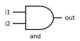
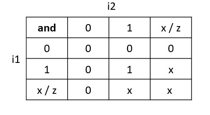
and | and g(out, i1, i2, …) | Performs AND operation on two or more inputs |
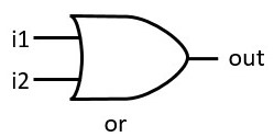
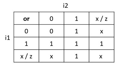
or | or g(out, i1, i2, …) | Performs OR operation on two or more inputs |
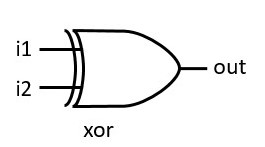
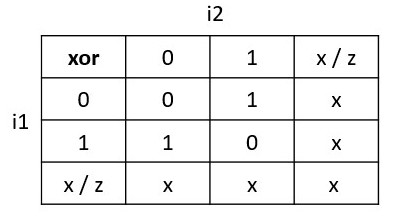
xor | xor g(out, i1, i2, …) | Performs XOR operation on two or more inputs |
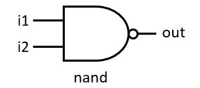
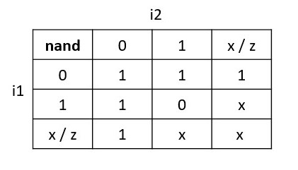
nand | nand g(out, i1, i2, …) | Performs NAND operation on two or more inputs |
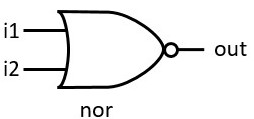
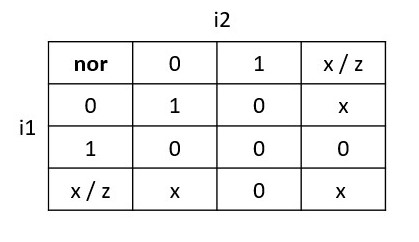
nor | nor g(out, i1, i2, …) | Performs NOR operation on two or more inputs |
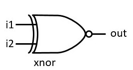
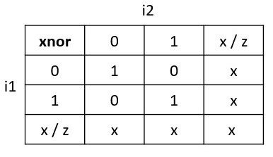
xnor | xnor g(out, i1, i2, …) | Performs XNOR operation on two or more inputs |
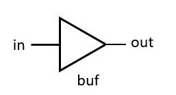
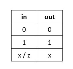
buf | buf g(out, in) | The buffer (buf) passes input to the output as it is. It has only one scalar input and one or more scalar outputs. |
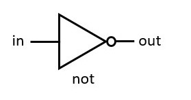
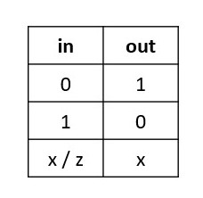
not | not g(out, in) | The not passes input to the output as an inverted version. It has only one scalar input and one or more scalar outputs. |
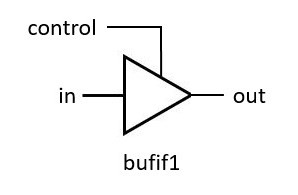
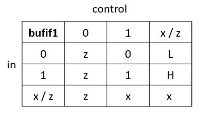
bufif1 | bufif1 g(out, in, control) | It is the same as buf with additional control over the buf gate and drives input signal only when a control signal is 1. |
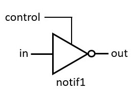
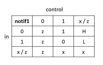
notif1 | notif1 g(out, in, control) | It is the same as not having additional control over the not gate and drives input signal only when a control signal is 1. |
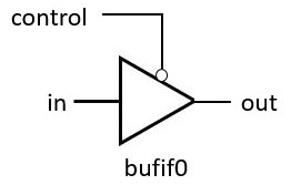
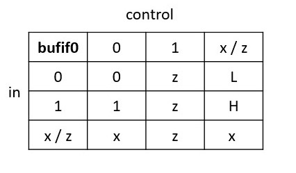
bufif0 | bufif0 g(out, in, control) | It is the same as buf with additional inverted control over the buf gate and drives input signal only when a control signal is 0. |
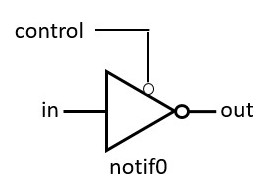
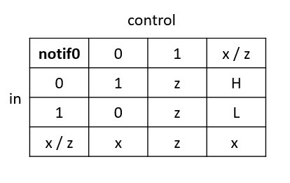
notif0 | notif0 g(out, in, control) | It is the same as not with additional inverted control over the not gate and drives input signal only when a control signal is 0. |
Note:
- bufif1 and notif1 provide ‘Z output when a control signal is 0.
- bufif0 and notif0 provide ‘Z output when a control signal is 1.
Symbols
Truth Table
Example for Gate level Modeling
module gate_modeling(
  input i1, i2, ctrl,
  output o_and, o_or,
  output o_nand, o_nor,
  output o_xor, o_xnor,
  output o_buf, o_not,

  output o_bufif1, o_notif1,
  output o_bufif0, o_notif0
  );

  // Gate types
  and  a1 (o_and , i1, i2);
  or   o1 (o_or  , i1, i2);
  nand na1(o_nand, i1, i2);
  nor  no1(o_nor , i1, i2);
  xor  x1 (o_xor , i1, i2);
  xnor xn1(o_xnor, i1, i2);

  // buffer and not
  buf(o_buf, i1);
  not(o_not, i1);

  // buffer and not with additional control
  bufif1(o_bufif1, i1, ctrl);
  notif1(o_notif1, i1, ctrl);

  bufif0(o_bufif0, i1, ctrl);
  notif0(o_notif0, i1, ctrl);
endmodule
Output:
0: i1 = 0, i2 = 0, ctrl = 0, o_and = 0, o_or = 0, o_nand = 1, o_nor = 1, o_xor = 0, o_xnor = 1, o_buf = 0, o_not = 1, o_bufif1 = z, o_notif1 = z, o_bufif0 = 0, o_notif0 = 1
1: i1 = 0, i2 = 1, ctrl = 1, o_and = 0, o_or = 1, o_nand = 1, o_nor = 0, o_xor = 1, o_xnor = 0, o_buf = 0, o_not = 1, o_bufif1 = 0, o_notif1 = 1, o_bufif0 = z, o_notif0 = z
2: i1 = 1, i2 = 0, ctrl = 0, o_and = 0, o_or = 1, o_nand = 1, o_nor = 0, o_xor = 1, o_xnor = 0, o_buf = 1, o_not = 0, o_bufif1 = z, o_notif1 = z, o_bufif0 = 1, o_notif0 = 0
3: i1 = 1, i2 = 1, ctrl = 1, o_and = 1, o_or = 1, o_nand = 0, o_nor = 0, o_xor = 0, o_xnor = 1, o_buf = 1, o_not = 0, o_bufif1 = 1, o_notif1 = 0, o_bufif0 = z, o_notif0 = z
Gate delays
In the real world, digital gates have delays involved for inputs propagating to the output with gate operation, and the same delay can be modeled in Verilog. A pin-to-pin delay can also be modeled in Verilog.
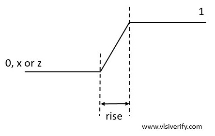
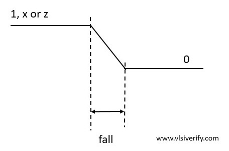
The three types of delays can be specified for delays from inputs to the primitive gate output as the rise, fall, and turn-off delays
Delays | Definition |
Rise delay | The delay associated or time is taken for the output of the gate to change to 1 from some value (0, x, or z). |
Fall Delay | The delay associated or time is taken for the output of the gate to change to 0 from some value (1, x, or z). |
Turn-off delay | The delay associated or time is taken for the output of the gate to change to z from some value. |
Rise delay
Fall delay
Delay specification types
Delay specification | Used for | Syntax |
One delay specification | all three transitions. | #(delay) |
Two delay specification | rise and fall transitions. | #(rise, fall) |
Three delay specification | rise, fall, and turn-off transitions. | #(rise, fall, turn-off) |
Example:
module gates (
  input i1, i2, ctrl,
  output y1, y2, out1, out2, out3);

  // #(3)     : delay = 3 for all transition
  // #(3,4)   : rise = 3, fall = 4
  // #(3,4,5) : rise = 3, fall = 4, turn-=off = 5

  or #(3) o1(y1, i1, i2);
  bufif1 #(3) b1(out1, i1, ctrl);

  or #(3,4) o2(y2, i1, i2);
  bufif1 #(3,4) b2(out2, i1, ctrl);

  bufif1 #(3,4,5) b3(out3, i1, ctrl);
endmodule
Output:
Time = 0: i1 = 1, i2 = 0, ctrl = 1
[single delay] y1 = x, out1 = x
[two delays] y2 = x, out2 = x
[Three delays] out3 = x


Time = 3: i1 = 1, i2 = 0, ctrl = 1
[single delay] y1 = 1, out1 = 1
[two delays] y2 = 1, out2 = 1
[Three delays] out3 = 1


Time = 10: i1 = 0, i2 = 1, ctrl = 1
[single delay] y1 = 1, out1 = 1
[two delays] y2 = 1, out2 = 1
[Three delays] out3 = 1


Time = 13: i1 = 0, i2 = 1, ctrl = 1
[single delay] y1 = 1, out1 = 0
[two delays] y2 = 1, out2 = 1
[Three delays] out3 = 1


Time = 14: i1 = 0, i2 = 1, ctrl = 1
[single delay] y1 = 1, out1 = 0
[two delays] y2 = 1, out2 = 0
[Three delays] out3 = 0


Time = 20: i1 = 0, i2 = 0, ctrl = 1
[single delay] y1 = 1, out1 = 0
[two delays] y2 = 1, out2 = 0
[Three delays] out3 = 0


Time = 23: i1 = 0, i2 = 0, ctrl = 1
[single delay] y1 = 0, out1 = 0
[two delays] y2 = 1, out2 = 0
[Three delays] out3 = 0


Time = 24: i1 = 0, i2 = 0, ctrl = 1
[single delay] y1 = 0, out1 = 0
[two delays] y2 = 0, out2 = 0
[Three delays] out3 = 0


xmsim: *W,RNQUIE: Simulation is complete.
Analysis:
Note the following delay types involved.
One delay : #(3) : delay = 3 for all transition
Two delay : #(3,4) : rise = 3, fall = 4
Three delay: #(3,4,5) : rise = 3, fall = 4, turn-=off = 5
Input driven: At time = 0: i1 = 1, i2 = 0, ctrl = 1
Since single delay = 3 and rise delay = 3, output y1, out1, y2, out2, out3 will be updated at 3 time units.
At time = 3:
[single delay] y1 = 1, out1 = 1
[two delays] y2 = 1, out2 = 1
[Three delays] out3 = 1
Input driven: Time = 10: i1 = 0, i2 = 1, ctrl = 1
An input i1 value is changed from 1 to 0 i.e. fall transition.
For single delay 3 units at time = 13, out1 is expected to change.
Time = 13:
[single delay] y1 = 1, out1 = 0
Outputs out2 and out3 are expected to change after a fall time delay which is 4 units.
Time = 14:
[two delays] y2 = 1, out2 = 0
[Three delays] out3 = 0
Input driven: Time = 20: i1 = 0, i2 = 0, ctrl = 1
An input i2 value is changed from 1 to 0 i.e. fall transition.
For single delay 3 units at time = 23, y1 is expected to change to 0.
Time = 23:
[single delay] y1 = 0, out1 = 0
Output y2 is expected to change after a fall time delay which is 4 units.
Time = 24:
[two delays] y2 = 0.
Additional controls min/ typ/ max values in delays
module gates (
  input i1, i2, ctrl,
  output y1, y2, out1, out2, out3);

  // #(3:4:5)   : delay(min = 3, typ = 4, max = 5) for all transition
  or #(3:4:5) o1(y1, i1, i2);
  bufif1 #(3:4:5) b1(out1, i1, ctrl);

  // #(3:4:5)   : rise delay (min = 3, typ = 4, max = 5)
  // #(4:5:6)   : fall delay (min = 4, typ = 5, max = 6)
  or #(3:4:5, 4:5:6) o2(y2, i1, i2);
  bufif1 #(3:4:5, 4:5:6) b2(out2, i1, ctrl);

  // #(3:4:5)   : rise delay (min = 3, typ = 4, max = 5)
  // #(4:5:6)   : fall delay (min = 4, typ = 5, max = 6)
  // #(5:6:7)   : Turn-off delay (min = 5, typ = 6, max = 7)
  bufif1 #(3:4:5, 4:5:6, 5:6:7) b3(out3, i1, ctrl);
endmodule
Verilog Tutorials