Modules and Ports in Verilog
Modules
A Module is a basic building design block in Verilog and it can be an element that implements necessary functionality. It can also be a collection of lower-level design blocks. As a part of defining a module, it has a module name, port interface, and parameters (optional). The port interface i.e. inputs and outputs is used to connect the high-level module with the lower one and hides internal implementation.
Declaration
The module is declared using a keyword ‘module’ with an optional port list and followed by its implementation. In the end, it is enclosed with the keyword ‘endmodule’.
module <module_name> (<port_list>);
  ...
  <implementation>
  ...
endmodule
A module consists of variable declaration, dataflow statements, behavioral blocks, instantiation of lower hierarchical modules, tasks, and functions. All of these are optional depending on the requirement statements or blocks that can be used, but module, endmodule, and module name are mandatory. It is not allowed to have nested modules; instead, it allows instantiating sub-module to have the module connections.
// This is illegal to write
module dut_1;
  ...
  module dut_2;
  ...
  endmodule
endmodule
Ports
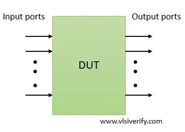
An interface to communicate with other modules or a testbench environment is called a port. In simple words, the input/ output pins of digital design are known as ports. This interface is termed a port interface or port list. Since the port list is available for connection, internal design implementation can be hidden from other modules or an environment.
Verilog keywords used for port declaration are as follows:
|
Port Type |
Keywords used |
Description |
|
Input port |
input |
To receive signal values from another module |
|
Output port |
output |
To send signal values to another module |
|
Bidirectional port |
inout |
To send or receive signal values to another module. |
Ports in Verilog
Example:
module mod(input a, b, output y);
...
endmodule
Note:
- Ports are of wire data type by default.
- If output ports hold their value, then they must be declared as reg data type.
- The input and inout ports can not be reg as they can not store values. Input ports pass signals from externally connected signals.
Connection rules in Verilog port
While writing a module, the designer needs to make sure what type of signals have to be connected to the module’s inputs and outputs and follow the below rules.
For understanding port connecting rules, consider the current design module as an internal world and outside of the module to be an external world.
|
Port type |
External world |
Internal world |
Description |
|
input |
reg or net |
net |
In an internal world, the input port must be of the net type and it can be connected to reg or net type variable in an external world. |
|
output |
net |
reg or net |
In an internal world, the output port can be of reg or net type and it must be connected to the net type variable in an external world. |
|
inout |
net |
net |
In an internal world, the inout port must be of the net type and it must be connected to the net type variable in an external world. |
Module instantiation
While designing complex digital circuits, usually it is split into various modules that connect to have a top-level block. Thus, Verilog supports a hierarchical design methodology. When a module is instantiated, a unique object is created and it has a unique name. Similarly, a top-level design can also be instantiated while creating a testbench.
module dut_1(<port_list>);
  ...
endmodule

module dut_2(<port_list>);
  ...
endmodule

module dut_3(<port_list>);
  dut_2 d2(...);
  ...
endmodule

// Top level module
module dut_top(<port_list>);
  dut_1 d1(...);
  dut_3 d3(...);
endmodule
Following the hierarchical approach, a particular signal can be reached out following hierarchy and each identifier is separated using a dot.
// Hierarchical connections
dut_top.d3.d2.<signal>  // To track a signal in dut_2 module.
A mechanism for connecting the port to the external signals
When a module is instantiated in the top-level hierarchy or top-level design in a testbench, any one of the following methods can be used.
Method A: Connecting a port list in an ordered manner
An ordered manner connection is feasible when a port list has minimum signals as the user has to follow the same order in which design level signals are declared.
Design declaration:
module mux_2_1(
  input sel,
  input i0, i1,
  output y);
Design instantiation in testbench:
module mux_tb;
  reg in0, in1, select;
  wire out;

  mux_2_1 mux(select, in0, in1, out);
        ...
endmodule
Observe that the port list in design mux_2_1 and its instantiation in testbench mux_tb follow the same order.
module mux_2_1(input sel, input i0, i1, output y); // At design
mux_2_1 mux(select, in0, in1, out); // At testbench
Note: It is not mandatory to use different names at the design and testbench level.
module mux_2_1(input sel, input i0, i1, output y); // At design
mux_2_1 mux(sel, i0, i1, y); // At testbench
Method B: Connecting a port list by name
For complex designs having more ports, remembering and writing in the same order while instantiating the design is error-prone. In this method, the order of port list connection does not matter based on the port name, the connection is established.
For an above example,
module mux_2_1(input sel, input i0, i1, output y); // At design
mux_2_1 mux(.i0(in0), .sel(select), .y(out), .i1(in1)); // At testbench
Verilog Tutorials