Implementation of sequential logic
Basic sequential logic implementation: D Flip flop
The D flip flop is a basic sequential element that has data input ‘d’ is being driven to output ‘q’ as per clock edge. Also, the D flip flop held the output value till the next clock cycle. Hence, it is called an edge-triggered memory element that stores a single bit.
Based on the type of D flip flop, a sensitive list of always block has to be written.
|
D Flip flop types |
Sensitivity list |
|
positive edge-triggered |
always @(posedge clk) |
|
negative edge-triggered |
always @(negedge clk) |
|
positive edge-triggered and asynchronous active high reset |
always @(posedge clk or posedge rst) |
|
positive edge-triggered and asynchronous active low reset |
always @(posedge clk or negedge rst) |
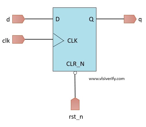
Positive edge-triggered and asynchronous active low reset D flip flop

Design schematic
module D_flipflop (
  input clk, rst_n,
  input d,
  output reg q
  );

  always@(posedge clk or negedge rst_n) begin
    if(!rst_n) q <= 0;
    else       q <= d;
  end

endmodule
Testbench:
module tb;
  reg clk, rst_n;
  reg d;
  wire q;

  D_flipflop dff(clk, rst_n, d, q);

  always #2 clk = ~clk;
  initial begin
    clk = 0; rst_n = 0;
    d = 0;

    #3 rst_n = 1;

    repeat(6) begin
      d = $urandom_range(0, 1);
      #3;
    end
    rst_n = 0; #3;
    rst_n = 1;
    repeat(6) begin
      d = $urandom_range(0, 1);
      #3;
    end
    $finish;
  end

  initial begin
    $dumpfile("dump.vcd");
    $dumpvars(1);
  end
endmodule
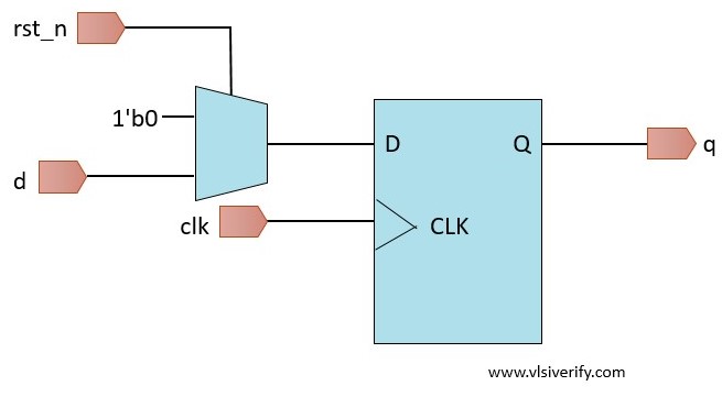
Positive edge-triggered and synchronous active low reset D flip flop

Design schematic
module D_flipflop (
  input clk, rst_n,
  input d,
  output reg q
  );

  always@(posedge clk) begin
    if(!rst_n) q <= 0;
    else       q <= d;
  end

endmodule
Testbench:
module tb;
  reg clk, rst_n;
  reg d;
  wire q;

  D_flipflop dff(clk, rst_n, d, q);

  always #2 clk = ~clk;
  initial begin
    clk = 0; rst_n = 0;
    d = 0;

    #3 rst_n = 1;

    repeat(6) begin
      d = $urandom_range(0, 1);
      #3;
    end
    rst_n = 0; #3;
    rst_n = 1;
    repeat(6) begin
      d = $urandom_range(0, 1);
      #3;
    end
    $finish;
  end

  initial begin
    $dumpfile("dump.vcd");
    $dumpvars(1);
  end
endmodule
Verilog Tutorials