User-defined Primitives (UDP)
Till now we have seen standard primitives supported by Verilog such as AND, OR, NOT, NAND, etc. However, Verilog also provides a facility to use their own customized primitives commonly known as User-defined Primitives (UDP).
- UDP can not instantiate other modules or primitives.
- UDPs are instantiated similar to gate-level primitives.
- They have exactly one output that can have either of these states 0, 1, or x. The high impedance z state can not be handled by UDP. For the given z input, it will be considered as x.
- They start with the primitive keyword and end with the endpremitive keyword. UDP can have multiple input ports but only one output port and UDP should not be declared inside the module block.
Syntax:
primitive <UDP name> ( <output name>, <input names>);

  // port declaration
  output <output name>;
  input <input names>;
  reg <output name>; // Applicable only for sequential UDP (optional)

  // UDP initialization
  initial <output name> = <value>; // Applicable only for sequential UDP (optional)

  // UDP state table
  table
    <table entries>
  endtable
endprimitive
UDP Rules
UDP follows the below rules
- UDP can have only scalar input terminals (1 bit), but multiple inputs are allowed.
- UDP can have only one scalar input terminal (1 bit) and it must be the first to appear in the terminal list. Multiple outputs are not allowed.
- The inputs and output are declared with input and output keywords respectively. The output for the sequential UDP must be declared as a reg.
- The initial statement is used to initialize the state of sequential UDP.
- UDPs are defined at the same level as modules and they can only be instantiated inside the module like gate primitive (can not be defined inside the module).
- Bidirectional port (inout) is not supported in UDP.
- The state table entries can have 0,1 or x value. The z value is not handled, but for the given z value, UDP treats it as an x value.
Following symbols are used to specify inputs and output values
|
Symbol |
Description |
|
0 |
Logic 0 |
|
1 |
Logic 1 |
|
x |
Unknown. It can be either logic 0 or 1 and can be used as input/output or the current state of sequential UDPs. |
|
? |
Logic 0, 1 or x. It can not be the output of UDP |
|
– |
No change, only allowed in the output of UDP |
|
ab |
Change in value from a to b where a or b is either 0, 1, or x |
|
* |
Same as ??, indicates any change in the input value |
|
r |
Same as 01 -> rising edge on input |
|
f |
Same as 10 -> falling edge on input |
|
p |
Potential positive edge on input. either 0->1, 0->x, or x->1 |
|
n |
Potential falling edge on input. either 1->0, x->0, 1->x |
Types of User-defined Primitives (UDP)
- Combinational UDP
- Sequential UDP
Combinational UDP
In combinational UDP, the logical combination of the inputs determines the output. On changing the state of the input, the output sets the value based on the state table row.
Maximum number of input supported: 10
Table in combinational UDP
The state table is written in the ‘table’ and ‘endtable’ keywords that enclose all possible combinations of the inputs and their corresponding output.
Syntax:
<input1> <input2> <input3> ... <inputN> : <output>;Example: 4:1 MUX with UDP
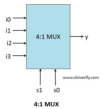
primitive mux_4_1 (y, s1, s0, i0, i1, i2, i3);
  //port declaration
  output y;
  input s1, s0;
  input i0, i1, i2, i3;

  table
    //s1  s0   i0   i1   i2   i3    :  y
      0    0    0    ?    ?    ?    :  0;
      0    0    1    ?    ?    ?    :  1;
      0    1    ?    0    ?    ?    :  0;
      0    1    ?    1    ?    ?    :  1;
      1    0    ?    ?    0    ?    :  0;
      1    0    ?    ?    1    ?    :  1;
      1    1    ?    ?    ?    0    :  0;
      1    1    ?    ?    ?    1    :  1;
      x    ?    ?    ?    ?    ?    :  x;
      ?    x    ?    ?    ?    ?    :  x;
  endtable
endprimitive

module udp_tb;
  reg s1, s0;
  reg i0,i1,i2,i3;
  wire y;

  mux_4_1 mux(y, s1, s0, i0, i1, i2, i3);

  initial begin
    $monitor("At time = %0t: {s1 = %b, s0 = %b} -> i3 = %0b, i2 = %0b ,i1 = %0b, i0 = %0b -> y = %0b", $time, s1,s0,i3,i2,i1,i0, y);
    {i3,i2,i1,i0} = 4'h5;
    repeat(6) begin
      {s1, s0} = $random;
      #5;
    end
    s1 = 1'bx; s0 = 1;
    #5;
    s1 = 0; s0 = 1'bx;
  end

endmodule
output:
At time = 0: {s1 = 0, s0 = 0} -> i3 = 0, i2 = 1 ,i1 = 0, i0 = 1 -> y = 1
At time = 5: {s1 = 0, s0 = 1} -> i3 = 0, i2 = 1 ,i1 = 0, i0 = 1 -> y = 0
At time = 15: {s1 = 1, s0 = 1} -> i3 = 0, i2 = 1 ,i1 = 0, i0 = 1 -> y = 0
At time = 20: {s1 = 0, s0 = 1} -> i3 = 0, i2 = 1 ,i1 = 0, i0 = 1 -> y = 0
At time = 30: {s1 = x, s0 = 1} -> i3 = 0, i2 = 1 ,i1 = 0, i0 = 1 -> y = x
At time = 35: {s1 = 0, s0 = x} -> i3 = 0, i2 = 1 ,i1 = 0, i0 = 1 -> y = x
Sequential UDP
In sequential UDP, the current input and the current output value determine the next output value. The sequential UDP provides an efficient interface for sequential circuits (i.e. flip-flops and latches) modeling.
- The output has to be declared as reg in sequential UDP
- To initialize the output of sequential UDP, use the initial keyword.
- Maximum number of input supported: 9 (since internal state treated as an input)
Table in sequential UDP
The state table is written in the table and endtable keywords that enclose all possible combinations of the inputs and their corresponding output.
Syntax:
<input1> <input2> <input3> ... <inputN> : <current_state> : <next_state>;Types of sequential UDP
- Level-sensitive sequential UDP
- Edge-sensitive sequential UDP
Level-sensitive sequential UDP
The sequential UDP which is sensitive to input level is called level-sensitive sequential UDP.
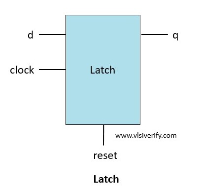
In this example,
If reset = 1, output q is always 0.
If reset = 0, output q = d
If clock = 0, output q retains its value.
primitive latch (q, clock, reset, d);
  //port declaration
  output reg q;
  input clock, reset, d;

  // initialization
  initial q = 0;
  table
    //clock   reset   d  :  q  :  q_next
        ?       1     ?  :  ?  :  0; // reset condition
        1       0     1  :  ?  :  1; // q = data
        1       0     0  :  ?  :  0; // q = data
        0       0     ?  :  ?  :  -; // retain previous state for clock = 0
  endtable
endprimitive

module udp_tb;
  reg clock, reset, d;
  wire q;

  latch lch(q, clock, reset, d);

  initial clock = 0;
  always #5 clock=~clock;

  initial begin
    $monitor("At time = %0t: clock = %b, reset = %b, d = %b, q = %b", $time, clock, reset, d, q);
    reset = 1;
    #10 reset = 0;
    d = 1;
    #20;
    d = 0;
    #10 $finish;
  end

endmodule
At time = 0: clock = 0, reset = 1, d = x, q = 0
At time = 5: clock = 1, reset = 1, d = x, q = 0
At time = 10: clock = 0, reset = 0, d = 1, q = 0
At time = 15: clock = 1, reset = 0, d = 1, q = 1
At time = 20: clock = 0, reset = 0, d = 1, q = 1
At time = 25: clock = 1, reset = 0, d = 1, q = 1
At time = 30: clock = 0, reset = 0, d = 0, q = 1
At time = 35: clock = 1, reset = 0, d = 0, q = 0
Simulation complete via $finish(1) at time 40 NS + 0Edge-sensitive sequential UDP
The sequential UDP which is sensitive to input edge transition called edge-sensitive sequential UDP.
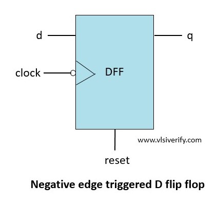
In this example,
If reset = 1, output q is always 0.
If reset = 0, output q = d on the negative transition of clock i.e. from 1 to 0.
If the clock changes to an unknown state, output q = no change
On the positive transition of the clock, output q = no change
|
Symbols |
Description |
|
(10) |
A negative edge transition from 1 to 0. |
|
(1x) |
A transition from 1 to x. |
|
(??) |
A transition from 0 to 1, 0 to x, 1 to 0, 1 to x or stable state. |
|
(0?) |
A transition from 0 to 0, 0 to 1 or 0 to x. |
primitive dff_nedge (q, clock, reset, d);
  //port declaration
  output reg q;
  input clock, reset, d;

  // initialization
  initial q = 0;
  table
    //clock   reset   d  :  q  :  q_next
        ?       1     ?  :  ?  :  0; // reset condition
        ?      (10)   ?  :  ?  :  -; // ignoring negative transiton of reset

      (10)      0     1  :  ?  :  1; // q = data
      (10)      0     0  :  ?  :  0; // q = data

      (1x)      0     ?  :  ?  :  -; // for unknown clock transition, hold previous state of q

      (0?)      0     ?  :  ?  :  -; // ignoring positive transiton of clock
      (x1)      0     ?  :  ?  :  -; // ignoring positive transiton of clock

       ?        0   (??) :  ?  :  -; // ignoring changes in d for no changes in clock
  endtable
endprimitive

module udp_tb;
  reg clock, reset, d;
  wire q;

  dff_nedge dff(q, clock, reset, d);

  initial clock = 0;
  always #5 clock=~clock;

  initial begin
    $monitor("At time = %0t: clock = %b, reset = %b, d = %b, q = %b", $time, clock, reset, d, q);
    reset = 1;
    #10 reset = 0;
    d = 1;
    #20;
    d = 0;
    #10 $finish;
  end

endmodule
At time = 0: clock = 0, reset = 1, d = x, q = 0
At time = 5: clock = 1, reset = 1, d = x, q = 0
At time = 10: clock = 0, reset = 0, d = 1, q = 0
At time = 15: clock = 1, reset = 0, d = 1, q = 0
At time = 20: clock = 0, reset = 0, d = 1, q = 1
At time = 25: clock = 1, reset = 0, d = 1, q = 1
At time = 30: clock = 0, reset = 0, d = 0, q = 1
At time = 35: clock = 1, reset = 0, d = 0, q = 1
Simulation complete via $finish(1) at time 40 NS + 0Verilog Tutorials