Tutorials
Learn More
System Verilog interface
Unlike Verilog that has module ports for communication, System Verilog provides an interface construct that simply contains a bundle of sets of signals. This encapsulates signals and communicates with design, testbench components.
Advantages of SystemVerilog interfaces
- In Verilog for the addition of new signals, it has to be manually changed everywhere that module has been instantiated. System Verilog made it easier to add new signals in the interface block for existing connections.
- It has increased re-usability across the projects.
- A set of signals can be easily shared across the components bypassing its handle.
- It provides directional information (modports) and timing information (clocking blocks).
- Interfaces can contain parameters, variables, functional coverage, assertions, tasks and functions.
- Interfaces can contain procedural initial and always blocks and continuous assign statements.
Syntax:
interface <interface_name>;
  ...
endinterface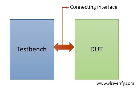
Writing an Interface
A basic interface
interface bus (input clk);
  logic [31:0] addr;
  logic [31:0] data;
  logic en;
endinterface
A parameterized interface
interface bus #(parameter WIDTH = 32)(input clk);
  logic [WIDTH-1:0] addr;
  logic [WIDTH-1:0] data;
  logic en;
endinterface
Full adder Example
To understand how interfaces can be used in the environment, a full adder is constructed using two half adders. In case any new signal has to be added (like enable), it can be easily added to the interface without touching the port list in the module.
Full adder example without using an interface
Design Code:
module half_addr(input a, b, output so, co);
  assign so = a^b;
  assign co = a & b;
endmodule

module full_adder(input a, b, c, output s_out, c_out);
  wire s0, c0, c1;
  half_addr HA1 (a, b, s0, c0);
  half_addr HA2 (s0, c, s_out, c1);

  assign c_out = c0 | c1;
endmodule
TB Code:
module tb_top;
  reg a, b, c;
  wire s, c_out;

  full_adder fa(a, b, c, s, c_out);

  initial begin
    $monitor("a=%b b=%b c=%b, sum=%b, carry=%b",a,b,c,s,c_out);
    a = 1; b = 0; c = 0;
    #1;
    a = 1; b = 0; c = 1;
    #1;
    a = 0; b = 1; c = 1;
  end
endmodule
Output:
a=1 b=0 c=0, sum=1, carry=0
a=1 b=0 c=1, sum=0, carry=1
a=0 b=1 c=1, sum=0, carry=1
Full adder example using an interface
Design Code:
module half_addr(input a, b, output so, co);
  assign so = a^b;
  assign co = a & b;
endmodule

module full_adder(fa_if inf);
  wire s0, c0, c1;
  half_addr HA1 (inf.a, inf.b, s0, c0);
  half_addr HA2 (s0, inf.c, inf.s_out, c1);

  assign inf.c_out = c0 | c1;
endmodule
TB Code:
interface fa_if;
  logic a, b, c;
  logic s_out, c_out;
endinterface

module tb_top;
  fa_if inf();
  full_adder fa(inf);

  initial begin
    $monitor("a=%b b=%b c=%b, sum=%b, carry=%b",inf.a,inf.b,inf.c,inf.s_out,inf.c_out);
    inf.a = 1; inf.b = 0; inf.c = 0;
    #1;
    inf.a = 1; inf.b = 0; inf.c = 1;
    #1;
    inf.a = 0; inf.b = 1; inf.c = 1;
  end
endmodule
Output:
a=1 b=0 c=0, sum=1, carry=0
a=1 b=0 c=1, sum=0, carry=1
a=0 b=1 c=1, sum=0, carry=1
Interface example using clk
Design Code:
module multiplier(mult_if inf);

  always@(posedge inf.clk or posedge inf.reset) begin
    if(inf.reset) begin
      inf.out <= 0;
      inf.ack <= 0;
    end
    else if(inf.en) begin
      inf.out <= inf.a * inf.b;
      inf.ack <= 1;
    end
    else inf.ack <= 0;
  end
endmodule
TB Code:
interface mult_if (input logic clk, reset);
  logic [7:0] a, b;
  logic [15:0] out;
  logic en;
  logic ack;
endinterface

module tb_top;
  bit clk;
  bit reset;

  always #2 clk = ~clk;

  initial begin
    clk = 0;
    reset = 1;
    #2;
    reset = 0;
  end

  mult_if inf(clk, reset);
  multiplier DUT(inf);

  initial begin
    #5;
    inf.a = 'd5; inf.b = 'd6;
    inf.en = 1;
    #10 inf.en = 0;
    wait(inf.ack);
    $display("%0t: a=%d b=%d, out=%d", $time, inf.a,inf.b,inf.out);

    #25;
    inf.a = 'd20; inf.b = 'd7;
    #5ns inf.en = 1;
    #6 inf.en = 0;
    wait(inf.ack);
    $display("%0t: a=%d b=%d, out=%d", $time, inf.a,inf.b,inf.out);

    #25;
    inf.a = 'd10; inf.b = 'd4;
    #6ns inf.en = 1;
    #5 inf.en = 0;
    wait(inf.ack);
    $display("%0t: a=%d b=%d, out=%d", $time, inf.a,inf.b,inf.out);
    #10;
    $finish;
  end

  initial begin
    $dumpfile("dump.vcd"); $dumpvars;
  end
endmodule
Output:
15: a=  5 b=  6, out=   30
51: a= 20 b=  7, out=  140
87: a= 10 b=  4, out=   40
Why is the logic data type used for the signal declaration or why bit data type is not used?
A bit data type is a 2-state data type that can have either 0 or 1 value. For incorrect RTL behavior like X or Z testbench would have sampled as 0. So, it needs a 4-state data type that can capture all 4 states 0, 1, X, or Z.
System Verilog Tutorials