Tutorials
Learn More
Writing a testbench in Verilog
The testbench is written to check the functional correctness based on design behavior. The connections between design and testbench are established using a port interface. A testbench generates and drives a stimulus to the design to check its behavior. Since the behavior of the design has to be tested, the design module is known to be “Design Under Test” (DUT).
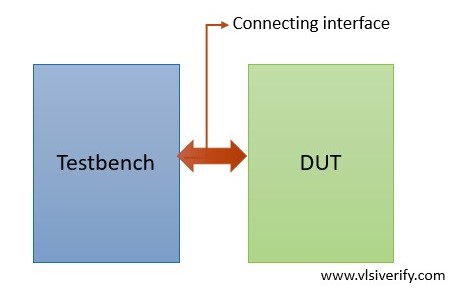
Connection between testbench and DUT
Let’s understand how to write Verilog testbench with a simple example of 2:1 MUX.
A 2:1 MUX is implemented using the ‘assign statement’ which will be discussed in the dataflow modeling section. For now, it is better to focus on how DUT is connected with a testbench and how the generated stimulus is driven.
module mux_2_1(
  input sel,
  input i0, i1,
  output y);

  assign y = sel ? i1 : i0;
endmodule
Steps involved in writing a Verilog testbench
i. Declare a testbench as a module.
module <testbench_name>;
Example: module mux_tb;
ii. Declare set signals that have to be driven to the DUT. The signals which are connected to the input of the design can be termed as ‘driving signals’ whereas the signals which are connected to the output of the design can be termed as ‘monitoring signals’. The driving signal should be of reg type because it can hold a value and it is mainly assigned in a procedural block (initial and always blocks). The monitoring signals should be of net (wire) type that get value driven by the DUT.
Note: The testbench signal nomenclature can be different the DUT port
reg i0, i1, sel; // declaration.
wire y;
iii. Instantiate top-level design and connect DUT port interface with testbench variables or signals.
<dut_module> <dut_inst> (<TB signals>)
mux_2_1 mux(.sel(sel), .i0(i0), .i1(i1), .y(y));
or
mux_2_1 mux(sel, i0, i1, y);
iv. Use an initial block to set variable values and it can be changed after some delay based on the requirement. The initial block execution starts at the beginning of the simulation and updated values will be propagated to an input port of the DUT. The initial block is also used to initialize the variables in order to avoid x propagation to the DUT.
Example: Initialize clock and reset variables.
initial begin
  clock = 0;
  reset = 0;
end
For 2:1 MUX example,
initial begin
    // To print the values.
    $monitor("sel = %h: i0 = %h, i1 = %h --> y = %h", sel, i0, i1, y);
    i0 = 0; i1 = 1;
    sel = 0;
    #1;
    sel = 1;
end
v. An always block can also be used to perform certain actions throughout the simulation.
Example: Toggling a clock
always #2 clock = ~ clock;In the above example, the clock is not used in the DUT, so we will not be declaring or using it.
vi. The system task $finish is used to terminate the simulation based on the requirement.
vii. The endmodule keyword is used to complete the testbench structure.
Complete testbench code
module mux_tb;
  reg i0, i1, sel;
  wire y;

  mux_2_1 mux(sel, i0, i1, y);
  initial begin
    $monitor("sel = %h: i0 = %h, i1 = %h --> y = %h", sel, i0, i1, y);
    i0 = 0; i1 = 1;
    sel = 0;
    #1;
    sel = 1;
  end
endmodule
Verilog Tutorials