Tutorials
Protocols
Learn More
Transfer Size and Strobes
AHB supports different transfer sizes on the same data bus. HSIZE defines the number of bytes in the transfer.
| HSIZE[2:0] | Transfer size | Bytes | Description |
|---|---|---|---|
| 000 | 8 bits | 1 | Byte transfer. Uses one byte lane selected by the address. |
| 001 | 16 bits | 2 | Halfword transfer. Uses two adjacent byte lanes and should be 2-byte aligned. |
| 010 | 32 bits | 4 | Word transfer. Uses four byte lanes and should be 4-byte aligned. |
| 011 | 64 bits | 8 | Doubleword transfer. Uses eight byte lanes on a 64-bit or wider data bus. |
| 100 | 128 bits | 16 | 16-byte transfer. Requires a data bus or width adapter that supports this size. |
| 101 | 256 bits | 32 | 32-byte transfer. Used only in systems with very wide data paths. |
| 110 | 512 bits | 64 | 64-byte transfer. Requires explicit wide-bus support. |
| 111 | 1024 bits | 128 | 128-byte transfer. Largest encoded AHB transfer size; legal only when supported by the implementation. |
The transfer size must be legal for the configured data bus. For example, a 32-bit data bus can naturally carry byte, halfword, and word transfers, but not a 64-bit single-beat transfer without width adaptation.
Address alignment
Address alignment means the start address must match the size of the transfer. In simple terms, an N-byte transfer must start on an N-byte boundary.
Rule: HADDR % number_of_transfer_bytes == 0
Equivalently, the lower address bits that select bytes inside the transfer must be zero. This lets the Subordinate select a clean group of byte lanes for the transfer.
| Transfer | Bytes | Required low address bits | Aligned examples | Not aligned |
|---|---|---|---|---|
| Byte | 1 | None | 0x1000, 0x1001, 0x1002 | Not applicable |
| Halfword | 2 | HADDR[0] = 0 | 0x1000, 0x1002, 0x1004 | 0x1001, 0x1003 |
| Word | 4 | HADDR[1:0] = 00 | 0x1000, 0x1004, 0x1008 | 0x1002, 0x1006 |
| Doubleword | 8 | HADDR[2:0] = 000 | 0x1000, 0x1008, 0x1010 | 0x1004, 0x100C |
| 16-byte transfer | 16 | HADDR[3:0] = 0000 | 0x1000, 0x1010, 0x1020 | 0x1008, 0x1018 |
For example, on a 64-bit data bus:
| Access | Meaning |
|---|---|
| Byte at 0x1003 | Valid. One byte lane is active. |
| Halfword at 0x1002 | Valid. Two adjacent byte lanes are active. |
| Halfword at 0x1003 | Not aligned, because HADDR[0] is 1. |
| Word at 0x1004 | Valid. Four adjacent byte lanes are active. |
| Word at 0x1002 | Not aligned, because HADDR[1:0] is not 00. |
| Doubleword at 0x1000 | Valid. All eight byte lanes of a 64-bit bus are active. |
AHB burst transfers must also obey this rule for every beat in the burst. The address increment is based on HSIZE, so a word burst increments by 4 bytes, a halfword burst increments by 2 bytes, and so on. For IDLE transfers, the specification recommends using aligned addresses to avoid unnecessary simulation warnings.
In practical RTL, unaligned accesses should be handled according to the design contract. A memory system might reject them, adapt them, or document that they are unsupported. Verification should include alignment tests because address and byte-lane bugs are common.
Write strobes
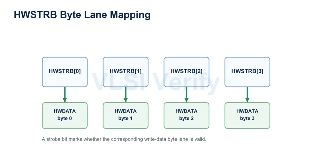
HWSTRB is an optional AHB5 feature. It lets a Manager update only selected bytes during a write transfer. It has one bit per byte lane of HWDATA.
HWSTRB[n] corresponds to HWDATA[(8n)+7:(8n)]. If HWSTRB[n] is HIGH, byte lane n is written. If it is LOW, that byte lane is not written.
The important point is that HWSTRB does not decide the transfer size. HSIZE and HADDR first decide which byte lanes are active for the transfer. HWSTRB then decides which of those active lanes are actually updated.
Sparse writes
A sparse write is a write transfer where at least one active byte lane has its strobe deasserted. The transfer is still a valid write transfer, but only the bytes with asserted strobes are updated.
For example, assume a 32-bit data bus and an aligned word write where byte lanes 0, 1, 2, and 3 are active:
| HWSTRB | Active byte lanes |
|---|---|
| 1111 | All four bytes are written. |
| 0001 | Only byte lane 0 is written. This is a sparse write. |
| 0010 | Only byte lane 1 is written. This is a sparse write. |
| 0100 | Only byte lane 2 is written. This is a sparse write. |
| 1000 | Only byte lane 3 is written. This is a sparse write. |
| 0101 | Byte lanes 0 and 2 are written. This is a sparse write. |
| 0000 | No bytes are written. This is permitted. |
Sparse writes are useful for byte-enable style memory updates, register fields, and masked writes where software wants to update part of a word without modifying the other bytes.
Write strobe rules
| Rule | Meaning |
|---|---|
| HSIZE and HADDR define active byte lanes | For transfers narrower than the data bus, the address and transfer size determine which lanes belong to the transfer. |
| Active-lane strobes can be HIGH or LOW | If an active lane strobe is HIGH, that byte is written. If it is LOW, that byte is not written, creating a sparse write. |
| Inactive-lane strobes can be HIGH or LOW | The receiver must still use HSIZE and HADDR to identify inactive lanes. An inactive lane must not be written just because its strobe is HIGH. |
| All strobes LOW is legal | The transfer completes, but no bytes are written. |
| Strobe-to-data-lane mapping is independent of endianness | HWSTRB[n] always maps to byte lane n of HWDATA; endianness changes byte significance, not the strobe bit mapping. |
| Read transfers should deassert strobes | Reads do not use write data byte lanes, so the recommended value is all strobes LOW. |
| Write burst strobes can change per beat | Each beat of a write burst can use a different HWSTRB value. |
| Strobes follow write-data timing | HWSTRB is associated with the write data phase and must remain stable during write wait states. |
This separation prevents a common bug: do not treat HWSTRB alone as the byte-lane mask. The legal byte lanes come from HSIZE and HADDR; the write strobes only enable or suppress writes inside that legal lane group.
Strobe interoperability
| Connection | Practical behavior |
|---|---|
| Manager with HWSTRB to Subordinate with HWSTRB | Sparse writes are supported. |
| Manager with HWSTRB to Subordinate without HWSTRB | Safe only if sparse writes are not required. |
| Manager without HWSTRB to Subordinate with HWSTRB | Treat all write byte lanes as active. |
| Neither side has HWSTRB | Every write is effectively a full-lane write for its transfer size. |
AHB Protocol